Lighting / Emergency Lighting
Eaton Supercharger 240VDC Installation Manual
Installation and configuration guide for the Eaton Supercharger 240VDC. Includes rack mounting instructions, electrical wiring diagrams, terminal block specifications, and setup procedures for EBM and external battery configurations.
Quick answers from the manual
Quick answer
- The Eaton Supercharger 240VDC is an accessory for Eaton 9SX and 9PX UPS models. It requires rack mounting, connection to AC input and DC output via terminal blocks, and manual configuration of battery settings (EBM or external battery) through the UPS interface. p. 1, 2, 3
Key actions
- Configure EBM settings p. 3
- Configure External Battery settings p. 3
Problems and fixes
Supercharger not recognized
Connect the RJ45 cable for automatic recognition.
p. 3Show 2 more answers Show less
Technical specifications
| Parameter | Value | Meaning | Pages |
|---|---|---|---|
| Weight | 15 kg / 33 lb | Unit weight | p. 1 |
| Dimensions | 700 x 440 x 130 mm | D x W x H | p. 1 |
| Operating Temperature | 0°C-40°C | Operating range | p. 1 |
| Input AC Protection | 20A | Recommended upstream protection | p. 4 |
| Battery Protection | 60A | Recommended battery protection | p. 4 |
Where to find it in the PDF
- Product Overview and Specifications p. 1
- Rear Panel Connections p. 2
- Configuration and Setup p. 3
- Wiring and Electrical Protection p. 4
Table of contents
Manual images
Click an image to enlargeQuick guide from the manual
The Eaton Supercharger 240VDC is designed for use with specific Eaton UPS models (9SX and 9PX series). The operating temperature range is 0°C to 40°C. Ensure all electrical connections are performed by qualified personnel and comply with local electrical codes.
Installation
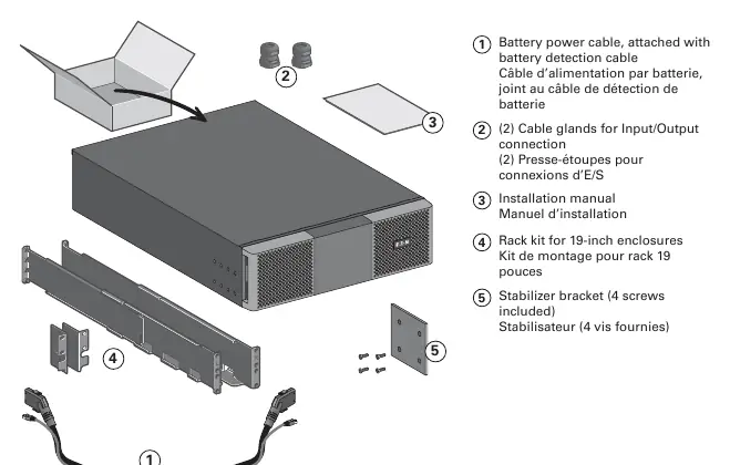
The unit is designed for 19-inch rack enclosures. Use the provided rack kit and stabilizer bracket to secure the unit. Ensure the unit is properly supported within the rack.
Connections
The rear panel features the following connections:
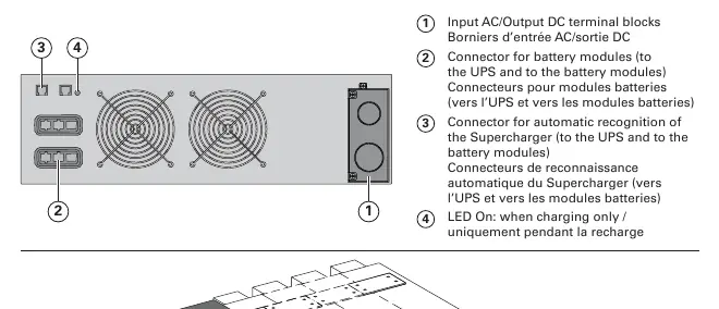
- Input AC/Output DC terminal blocks: Used for power connections.
- Battery module connector: Connects to the UPS and battery modules.
- Automatic recognition connector: RJ45 port for automatic Supercharger recognition by the UPS.
Configuration
After physical installation, configure the settings via the UPS interface:
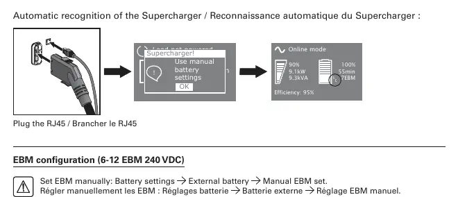
- EBM Configuration (6-12 EBM 240 VDC): Navigate to Battery settings -> External battery -> Manual EBM set.
- External Battery Configuration (50Ah – 400Ah / 240VDC): Navigate to Battery settings -> External battery -> Manual battery set.
Always refer to the battery manufacturer’s instructions regarding specific battery precautions.
Electrical Specifications
Proper protection devices must be provided by the installer for permanently connected AC input and DC output circuits:
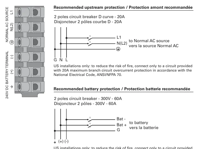
- Recommended upstream protection (AC): 2 poles circuit breaker, D curve, 20A.
- Recommended battery protection (DC): 2 poles circuit breaker, 300V, 60A.
- Tightening torque: 10 lb in / 1.13 Nm for all terminal connections.
Manufacturer information
Eaton
Practical help
Common problems
Supercharger not recognized by UPS
Ensure the RJ45 cable is securely connected to the automatic recognition port.
Incorrect EBM count or battery capacity
Manually configure the settings in the UPS menu under Battery settings -> External battery.
Before use
- Verify UPS compatibility (9SX8KiPM, 9SX11KiPM, 9PX8KPM, 9PX11KPM, 9PX8KiPM, 9PX11KiPM, 9PX6KiPM31, 9PX8KiPM31, 9PX11KiPM31)
- Ensure operating environment is between 0°C and 40°C
- Install rack kit for 19-inch enclosures
- Install stabilizer bracket
- Prepare 20A D-curve circuit breaker for AC input
- Prepare 60A 300V circuit breaker for battery protection
Show more Show less
Specs in practice
- Tightening torque
- 10 lb in / 1.13 Nm required for all terminal block screws.
- Input AC wire size
- Minimum 4 mm² (12 AWG) at 75°C.
- Output DC wire size
- Minimum 16 mm² (6 AWG) at 90°C.
Images and diagrams
- The rear panel diagram identifies the terminal blocks, battery module connectors, and the RJ45 recognition port.
- Wiring diagrams illustrate the connection to the Normal AC source and the battery bank with required circuit breakers.
Model compatibility
- Compatible with 9SX8KiPM, 9SX11KiPM, 9PX8KPM, 9PX11KPM, 9PX8KiPM, 9PX11KiPM, 9PX6KiPM31, 9PX8KiPM31, 9PX11KiPM31.

Manual page author
Michael Turner
Technical manual editor