Lighting / Emergency Lighting
Installation and Operation Manual for VoCALL 16US Emergency Communication System
Comprehensive installation and operation guide for the Eaton VoCALL 16US 2-Way Emergency Communication System. Includes wiring diagrams, system configuration, programming steps, and troubleshooting.
Quick answers from the manual
Quick answer
- The VoCALL 16US is a digital, loop-wired emergency communication system. Configuration involves setting up the Main Panel (MX16US), performing a Call Station Learn, and optionally configuring a Network Panel (NX16US) and Gateway Dialer. p. 14, 47
Key actions
- Perform Call Station Learn p. 65
- Perform System Learn p. 90
First start
- Login as ENGINEER 2 using default PIN 999999. p. 48
Problems and fixes
Loop Break
Check wiring continuity between panels.
p. 92Maintenance and reset
- Acknowledge faults to silence the buzzer for 24 hours. p. 46
Technical specifications
| Parameter | Value | Meaning | Pages |
|---|---|---|---|
| Power Supply | 120 Vac | 120 Vac (+ 10%/ -15%), 60Hz | p. 17 |
Where to find it in the PDF
- Installation p. 26
- Operations p. 42
Table of contents
Manual images
Click an image to enlargeQuick guide from the manual
The VoCALL 16US is a digital, loop-wired emergency communication system. This manual provides essential instructions for installation, wiring, system configuration, and maintenance. The system requires professional installation by trained personnel and must be installed in restricted access areas.
System Overview
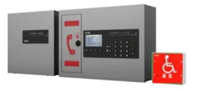
The system consists of the MX16US Main Panel, optional NX16US Network Panels, and remote Call Stations. It supports up to 160 Call Stations in a networked configuration. The system is fully addressable and monitored, providing bi-directional communication.
Installation
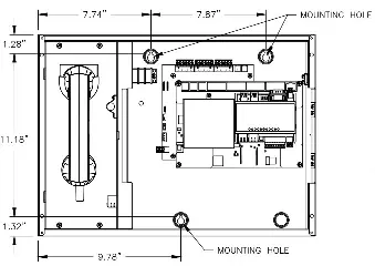
The MX16US and NX16US panels should be mounted in restricted access areas to prevent tampering. The MX16US should be mounted at a height of 48-60 inches, while the NX16US should be at 36-66 inches. Call Stations should be mounted at 34-48 inches above the floor in areas of refuge or near elevator landings.
Wiring
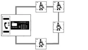
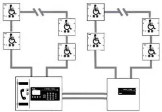
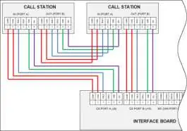
All wiring must be shielded. Power-limited and non-power-limited wiring must be separated within the enclosures. The system uses a daisy-chain loop configuration for both Call Stations and panels, providing survivability for a single fault.
Operations
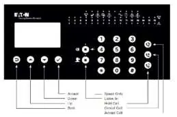
The MX16US front panel features an LCD display, keypad, and status LEDs. Users can manage calls, view logs, and configure system parameters. The system supports one active voice call at a time. Incoming calls are logged, and the system can be configured to route calls to an off-premise location via the Gateway Dialer.
Programming
System configuration is performed via the MX16US keypad. Key steps include:
- Logging in as ENGINEER 2 (default PIN 999999).
- Configuring the Main Panel settings.
- Performing a Call Station Learn to auto-address connected stations.
- Performing a System Learn to identify networked panels.
Web Server & SD Card Explorer
The system includes a web server for remote configuration and an SD Card Explorer utility for managing logs and Text-to-Speech (T2S) messages. T2S allows the system to play unique location-specific voice messages during emergency events.
Troubleshooting
The system provides detailed fault logs. Common issues include loop breaks, missing panels, or dialer communication errors. Faults can be viewed on the front panel, via the web server, or using the SD Card Explorer log viewer.
Manufacturer information
Eaton
Practical help
Common problems
Audio File Missing
Run a Sysconfig.Backup; the fault will be resolved when audio messages are programmed.
Loop Break
Check wiring continuity between panels; the Main panel will indicate the location of the break.
Dialer Not Found
Check Ethernet connection and network settings on the Dialer.
Ground Fault
Remove and reinsert the CON8 Earth Ground jumper on the Mainboard.
Before use
- Verify system is installed and powered (AC and Power LEDs green).
- Ensure all devices are connected via shielded cable.
- Check that the SD Card is installed in the MX16US.
- Ensure all Call Stations have the same software version.
- Login as ENGINEER 2 (default PIN 999999).
Specs in practice
- Operating Temperature
- 32°F to 98°F (0°C to 37°C).
- Power Supply
- 120 Vac (+10%/-15%), 60Hz.
- Network Configuration
- Loop wired - isolated Class X without ground fault detection.
Images and diagrams
- Figure 21: Daisy chain loop for Call Station wiring.
- Figure 23: Daisy chain loop for panel wiring.
- Figure 26: Relay wiring to FACP.
- Figure 27: Dialer Wiring.
Model compatibility
- Requires shielded cable for all network and Call Station wiring.
- Network cabling must be CAT 5e (10/100 Mbps) minimum.
- Ethernet connectors must be unshielded with non-metallic hoods.

Manual page author
Michael Turner
Technical manual editor
Reviews PDF manuals for structure, safety notes, and practical product details so readers can find the right information quickly.