Lighting / Emergency Lighting
User Manual for Eaton FlexiTech Exit Wall 20M/30M CGLine+
Comprehensive user guide for the Eaton FlexiTech Exit Wall 20M/30M CGLine+ emergency luminaire. Includes installation instructions, wiring diagrams, configuration settings, magnet test procedures, and technical specifications.
Quick answers from the manual
Quick answer
- The Eaton FlexiTech Exit Wall 20M/30M CGLine+ is an emergency luminaire. Installation involves drilling, wiring, and configuring settings via DIP switches. Testing is performed using a magnet. p. 1, 2, 4
Key actions
- Install the luminaire using the provided drilling template and cable entries. p. 1
- Configure duration and light level using the DIP switches. p. 2
- Perform tests using a magnet. p. 4
First start
- Connect the battery and ensure the device is wired correctly according to the diagram. p. 2
Problems and fixes
Battery duration is insufficient
Replace the battery pack (FT-BATLL2).
p. 5, 9Maintenance and reset
- Reset luminaire using a magnet (hold for 10-20 seconds). p. 4
Technical specifications
| Parameter | Value | Meaning | Pages |
|---|---|---|---|
| Voltage | 230V ~ / 50-60Hz | Operating voltage | p. 5 |
| Battery | Li 3.2V 1.5Ah | Battery specifications | p. 5 |
Where to find it in the PDF
- Installation p. 1
- Wiring and Configuration p. 2
- Testing and Maintenance p. 3, 4
- Technical Specifications p. 5
Table of contents
Manual images
Click an image to enlargeQuick guide from the manual
The Eaton FlexiTech Exit Wall 20M/30M CGLine+ is an emergency exit luminaire. Key operations include physical installation, electrical wiring, configuration of duration and light levels via DIP switches, and periodic testing using a magnet. Ensure the battery is connected before operation.
Installation
The luminaire can be mounted on walls. Follow these steps for installation:
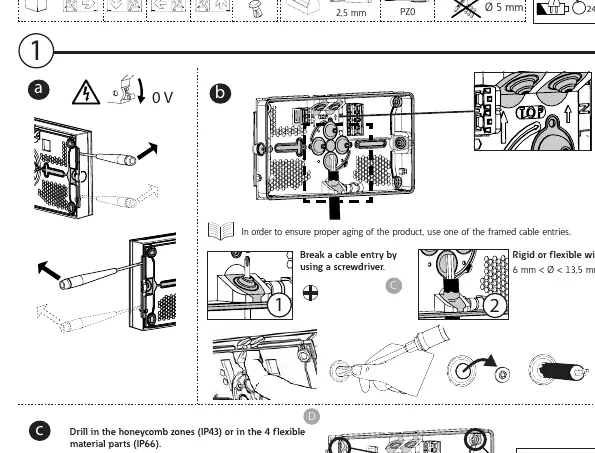
- Cable Entry: Break a cable entry using a screwdriver. Use one of the framed cable entries to ensure proper aging of the product.
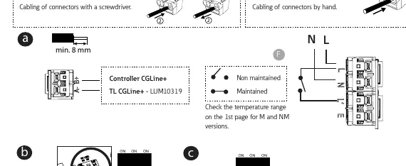
- Drilling: Drill in the honeycomb zones (IP43) or in the 4 flexible material parts (IP66). Be careful of the battery location when drilling in honeycomb zones.
- Fixing: For corner fixing, use 4 screws.
Electrical connection
Ensure the power is off (0V) before starting. The device supports rigid or flexible wire (6 mm < Ø < 13,5 mm). Cabling of connectors can be done with a screwdriver or by hand (0,5 < S < 2,5 mm²). Connect the battery and wait 10 seconds before reconnecting if you change the configuration.
Configuration
The device allows for specific configurations using DIP switches:
- Light Level: Set the light level to 50 cd/m² (OFF) or 500 cd/m² (ON).
- Duration: Configure the duration (1h, 2h, 3h, 8h) using the DIP switches.
- Even/Odd: Set the duration test day. Disconnect the battery, wait 10 seconds, and reconnect to apply changes.
Magnet test
Use a magnet to perform tests and adjustments:
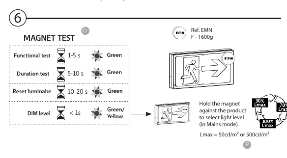
- Functional test: Hold magnet for 1-5 seconds.
- Duration test: Hold magnet for 5-10 seconds.
- Reset luminaire: Hold magnet for 10-20 seconds.
- DIM level: Hold magnet for < 1 second to select light level (in Mains mode).
Maintenance
The battery and light source are critical components:
- Battery: If battery duration is insufficient, replace the battery pack (Order code: FT-BATLL2).
- Light Source: When the lifetime of the light source is over, replace the entire luminaire.
- LED Status: Green constant (OK), Green blinking (TEST), Green & Yellow (COM), Yellow constant (2s), Yellow blinking (0,5s).
Technical specifications
The device operates at 230V ~ / 50-60Hz. Available models include 20M and 30M versions with IP43 or IP66 ratings. Battery type is Li 3.2V 1.5Ah.
Manufacturer information
Eaton
Practical help
Common problems
Insufficient battery duration
Replace the battery pack (Order code: FT-BATLL2).
Light source failure
When the lifetime of the light source is over, replace the luminaire.
Configuration changes not applying
Disconnect the battery, wait for 10 seconds, and reconnect it.
Before use
- Check the temperature range on the 1st page for M and NM versions.
- Ensure the battery is connected.
- Verify the cable entry is properly broken for wiring.
- Confirm the IP rating (IP43 or IP66) matches your installation environment.
Specs in practice
- 230V ~ / 50-60Hz
- Standard electrical supply requirements.
Images and diagrams
- Page 1 shows drilling locations and cable entry preparation.
- Page 2 details the wiring diagram and DIP switch settings for duration and light level.
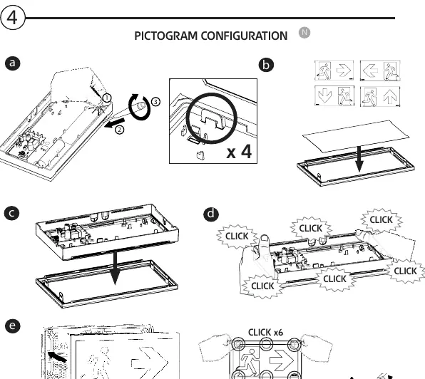
- Page 3 illustrates the pictogram configuration and LED status indicators.
- Page 4 explains the magnet test procedures.
Model compatibility
- Compatible with Controller CGLine+ for advanced settings.
- Battery pack order code: FT-BATLL2.

Manual page author
Michael Turner
Technical manual editor
Reviews PDF manuals for structure, safety notes, and practical product details so readers can find the right information quickly.