Industrial / Electrical
Technical Manual for Eaton XB15 and XB15M Xenon Beacons
Comprehensive technical manual for the Eaton XB15 and XB15M Xenon Beacons. This guide covers installation, wiring diagrams, maintenance procedures, safety certifications for explosive atmospheres, and functional safety specifications.
Table of contents
Manual images
Click an image to enlargeQuick Guide from the Manual
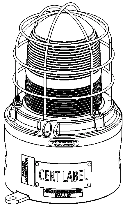
The Eaton XB15 and XB15M are xenon beacons designed for use in potentially explosive atmospheres and harsh environmental conditions. Before installation, ensure the power is isolated. For EN54-23 compliance, the mounting back strap must be positioned in the horizontal plane. Always use stainless steel fasteners and ensure all nuts, bolts, and fixings are secure.
Installation
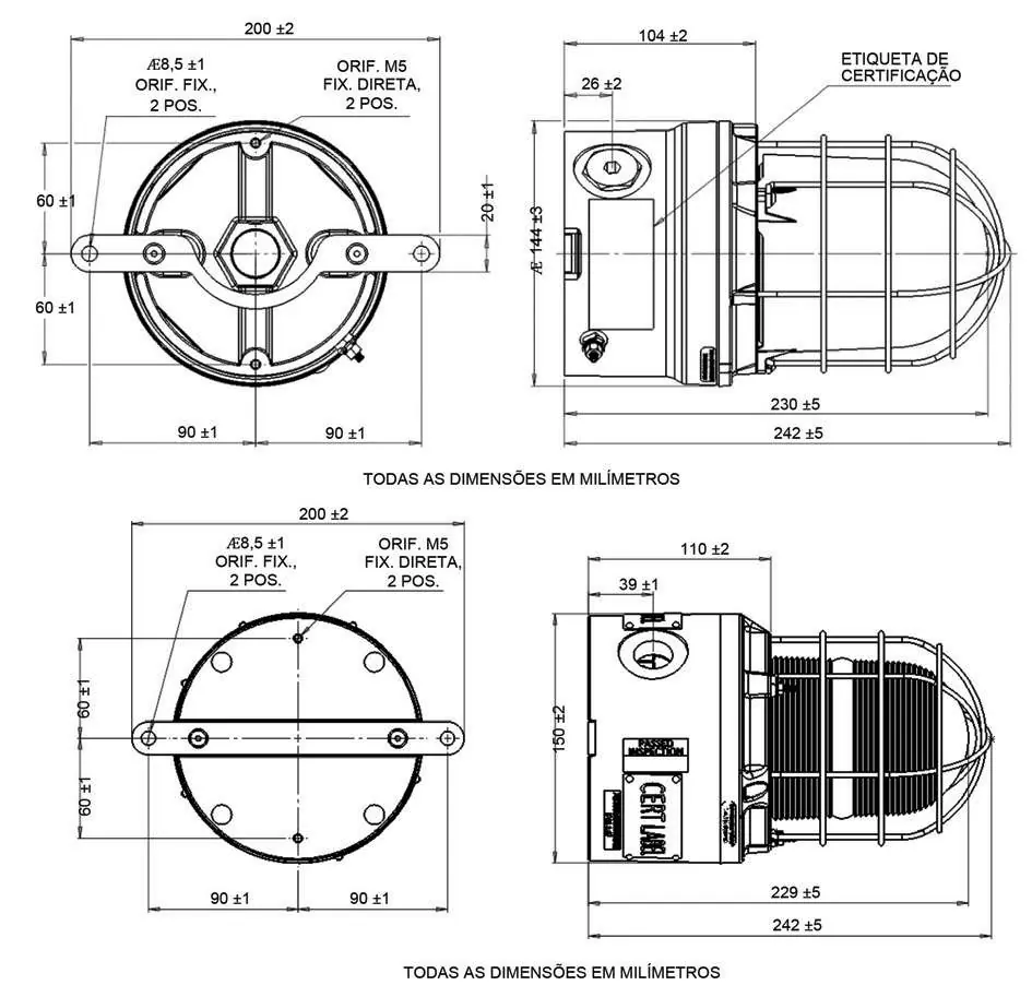
The device can be mounted directly using inserts in the back of the enclosure or via an optional backstrap. For direct mounting, use the following formula to determine the required fixing screw length: Length of screw = Thickness of mounting surface + 10mm. The mounting holes in the optional backstrap are designed for M8 screws.

Access to Terminals
To access the terminals, first ensure power is isolated. Unscrew the grub screw (2.0mm A/F hexagon key) in the cover flange by 3 full turns (do not fully unscrew). Unscrew and remove the cover and lens assembly using the supplied spanner. Carefully lift the PCB assembly clear of the mounting pillars. After termination, replace the PCB assembly, tighten the thumbscrews, and re-secure the cover.
Wiring
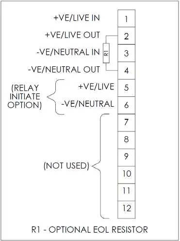
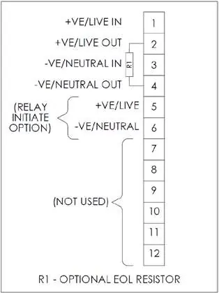
The wiring detail provides connections for power and relay initiation. Monitoring resistors may be fitted to DC units. Ensure all cables and cores are correctly identified and terminated in accordance with the wiring diagram provided in the manual.
Operation
The beacon can be powered directly or initiated by a 24Vdc relay or telephone ringing signal if requested. The flash rate is pre-set by the manufacturer and cannot be adjusted. For EN54-23:2010 compliance, only the 24Vdc, 60 fpm version (with clear or red lens) is approved.
Maintenance
The unit requires little maintenance. If cleaning is necessary, use only a damp cloth to avoid electrostatic charge build-up. If the cover/lens assembly grease needs re-application, use a PFPE-based grease such as Krytox GPL203 or Perfluorolube 22/6 to prevent O-ring damage. Xenon tube replacement can be performed by competent site personnel.
Safety and Certification
The device is certified for use in explosive atmospheres (ATEX/IECEx). It is rated for SIL 2 functional safety. Do not open the device when an explosive atmosphere is present. Ensure all cable entries and stopping plugs are sealed to maintain the IP6X rating.
Manufacturer information
Eaton
Practical help
Common problems
Unit not flashing
Verify power supply and wiring connections. Ensure the correct voltage is applied to the unit.
Difficulty removing cover
Ensure the grub screw (2.0mm A/F hexagon key) has been unscrewed 3 full turns before attempting to remove the cover.
Electrostatic charge risk
Clean the exterior only with a damp cloth. Protect the unit from direct airflow from exhaust ducts.
Before use
- Ensure power to the device is isolated before removing the cover.
- Verify that the mounting surface is horizontal for EN54-23 compliance.
- Check that cable glands and stopping plugs are correctly listed or certified.
- Ensure the device is fully sealed and secured before applying power.
- Verify that the unit is correctly earthed.
Images and diagrams
- The wiring detail shows terminals 1-12 for power input/output and relay initiation options.
- General arrangement diagrams provide dimensions for direct mounting and backstrap installation.
Model compatibility
- EN54-23 compliance requires the 24Vdc, 60 fpm version with a clear or red lens.
- Monitoring resistors must be fitted to DC units as specified in the manual.

Manual page author
Emily Carter
User documentation editor
Prepares concise manual descriptions and highlights the most useful setup, operation, and maintenance information for readers.