Industrial / Circuit Breakers
Installation Guide for Eaton FRCdM-Type B 2-Pole Residual Current Device
Installation and wiring guide for the Eaton FRCdM-Type B 2-pole Residual Current Device (RCCB). Includes mounting instructions, wiring diagrams, safety warnings for insulation testing, and technical specifications.
Quick answers from the manual
Quick answer
- The Eaton FRCdM-Type B is a 2-pole Residual Current Device. Installation requires mounting on a 35mm DIN rail, proper wiring of main and auxiliary terminals, and mandatory disconnection of the load side during insulation testing. p. 1
Key actions
- Disconnect load side during insulation testing p. 1
- Test the device functionality p. 1
First start
- Mount on 35mm DIN rail and connect cables p. 1
Problems and fixes
Test button not working
Check if voltage is between 196V and 264V AC. Minimum voltage for Type B functionality is 50V AC.
p. 1Maintenance and reset
- Reset the device by moving the switch to the ON position after testing. p. 1
Technical specifications
| Parameter | Value | Meaning | Pages |
|---|---|---|---|
| Rated Current (In) | 16-63A | Operating current range | p. 1 |
| Max back-up fuse | 63A gG/gL | Required protection | p. 1 |
Where to find it in the PDF
- Installation and Wiring Guide p. 1
Table of contents
Manual images
Click an image to enlargeImportant Safety Information
WARNING: You must disconnect the load side of the switchgear before performing any insulation test on the installation. Failure to do so may damage the device.
Mounting
The device is designed for mounting on a standard 35mm DIN rail. Ensure the device is securely clicked into place. The installation must be performed by qualified personnel in accordance with local electrical regulations.
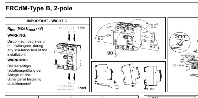
Wiring
Follow the connection diagrams provided on the device label. Ensure proper torque is applied to the terminals.
- Main Terminals: Suitable for wire cross-sections between 1.5mm² and 35mm². Tightening torque: 2 - 2.4 Nm.
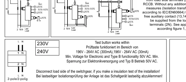
- Auxiliary Contact (13, 14): Provides a potential-free contact with basic insulation from the load side terminals (2N). Suitable for wire cross-sections between 0.25mm² and 1.5mm².
Operation and Testing
The test button is used to verify the functionality of the RCCB. The test button works within the voltage range of 196V - 264V AC. The minimum voltage required for electronic and Type B functionality is 50V AC.
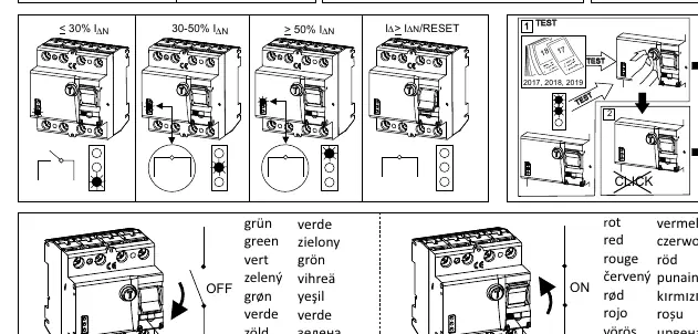
To test, press the test button. The device should trip (switch to OFF position). Reset the device by moving the switch to the ON position.
Technical Specifications
- Rated Current (In): 16-63A
- Maximum Back-up Fuse: 63A gG/gL
- Auxiliary Contact Rating: 0.25A (ohmic) at 240V~
Manufacturer information
Eaton
Practical help
Common problems
Insulation test failure
Disconnect the load side of the switchgear before performing any insulation test on the installation.
Test button does not trip
Ensure the supply voltage is within the operating range (196V-264V AC). Minimum voltage for Type B functionality is 50V AC.
Before use
- Verify the DIN rail is 35mm.
- Ensure wire cross-section for main terminals is between 1.5mm² and 35mm².
- Ensure wire cross-section for auxiliary terminals is between 0.25mm² and 1.5mm².
- Check that the supply voltage is within the operating range.
- Ensure the load side is disconnected if performing insulation tests.
Specs in practice
- In (Rated Current)
- The operating current range of the device (16-63A).
- Max back-up fuse
- The maximum rating of the fuse required to protect the device (63A gG/gL).
- Auxiliary contact (13, 14)
- A potential-free contact used for signaling, isolated from the load side.
Images and diagrams
- The wiring diagram shows the connection of Line and Load terminals.
- The auxiliary contact (13, 14) must be wired according to the specific isolation requirements shown in the diagram.
- The test sequence diagram illustrates the manual operation of the test button.
Model compatibility
- Type B functionality requires a minimum voltage of 50V AC.
- The auxiliary contact (13, 14) provides only basic insulation from load side terminals (2N).

Manual page author
Michael Turner
Technical manual editor
Reviews PDF manuals for structure, safety notes, and practical product details so readers can find the right information quickly.