Lighting / Emergency Lighting
Installation and Technical Guide for Eaton ICON 185-500A Contactors
A comprehensive installation and technical guide for Eaton ICON 185-500A contactors. This manual covers technical specifications, wiring diagrams, accessory compatibility, operating conditions, and dimensional data for the Baseline and...
Quick answers from the manual
Quick answer
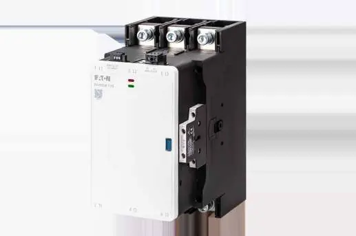
- The Eaton ICON 185-500A series are high-performance contactors for motor control, featuring built-in fault and life diagnostics. They are available in Baseline and Advanced versions, with the latter supporting direct PLC control. p. 3
Key actions
- Wiring for PLC control (Advanced version) p. 7
First start
- Verify voltage and control method p. 4, 7
Problems and fixes
Electrical interference
Apply suppression measures if used in residential environments.
p. 22Technical specifications
| Parameter | Value | Meaning | Pages |
|---|---|---|---|
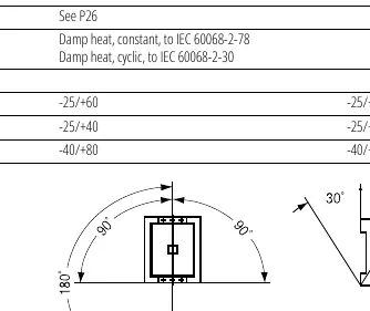
| Ambient temperature (open) | -25/+60 °C | Operating temperature range | p. 14 |
Where to find it in the PDF
- Technical Overview p. 3, 4
- Accessories p. 8, 9, 10, 11
- Technical Data p. 14, 15, 16, 17
- Dimensions p. 27
Table of contents
Manual images
Click an image to enlargeQuick guide from the manual
The Eaton ICON 185-500A series contactors are designed for high-performance motor control. They feature built-in fault and life diagnostic functions with LED status indicators. The series is divided into Baseline and Advanced versions, with the Advanced version supporting direct PLC control. Ensure you identify your specific model (e.g., DILM185N, DILM500-11N) to verify compatibility with accessories and control methods.
Technical overview
The contactors are designed for various utilization categories:
- AC-3: For squirrel cage motors (starting, switching off motors during running).
- AC-4: For squirrel cage motors (jogging, plugging, reversing).
- AC-1: For non-inductive or slightly inductive loads (e.g., electrical heating).
Wiring and control
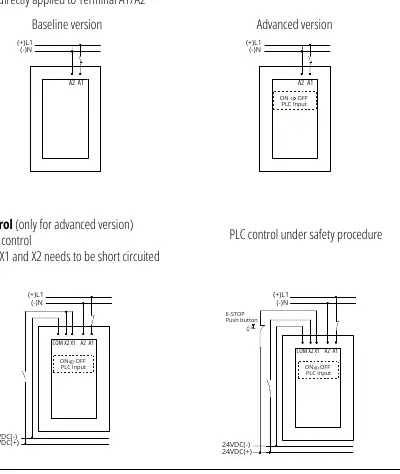
The contactors support universal AC and DC control coils. For the Advanced version, direct PLC control is possible. Important: When using direct PLC control, terminals X1 and X2 must be short-circuited. Conventional control is achieved by applying voltage directly to terminals A1/A2.

Accessories
A wide range of accessories is available to customize the installation, including:
- Star-point bridges and Reversing kits: For specific motor starting configurations.
- Mechanical interlocks: Allow for interlocking two contactors (vertical or horizontal mounting). Note: Contactor spacing must be 32.1mm.
- Cable wiring terminals: Available for various conductor cross-sections (50mm² to 240mm²).
- Terminal protective covers: Prevent direct vertical contact with the terminal.
Operating conditions and safety
The devices are intended for industrial environments (Environment 2). If used in residential environments (Environment 1), appropriate electrical interference suppression measures must be taken. The ambient temperature range for open installation is -25°C to +60°C.
Technical data
Key technical parameters include:
- Protection degree: IP00.
- Mechanical lifespan: 8 x 10⁶ operations.
- Mounting positions: Refer to the mounting position diagrams in the technical data section for allowed angles.
Manufacturer information
Eaton
Practical help
Common problems
Electrical interference in residential areas
The device is designed for industrial environments. If used in residential areas, you must apply appropriate suppression measures.
PLC control not functioning
For Advanced versions, ensure that terminals X1 and X2 are short-circuited when using direct PLC control.
Before use
- Verify the rated operating voltage matches your application requirements.
- Confirm whether you are using the Baseline or Advanced version.
- Ensure the ambient temperature is within the -25°C to +60°C range for open installations.
- Check that wiring terminal markings match your circuit design.
- Ensure proper spacing (32.1mm) if using mechanical interlocks.
Images and diagrams
- Wiring diagrams for conventional and PLC control are located on page 7.
- Mounting position diagrams are provided on page 14.
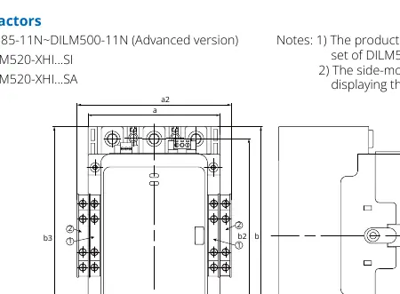
- Dimensional drawings for all models are available on page 27.
Model compatibility
- Accessories like star-point bridges and reversing kits are model-specific; verify the 'Applicable contactor' column on pages 8-9.
- Mechanical interlocks cannot have auxiliary contact modules installed between the interlock and the contactor.

Manual page author
Emily Carter
User documentation editor
Prepares concise manual descriptions and highlights the most useful setup, operation, and maintenance information for readers.