Power / Batteries & Chargers
User Manual for ePropulsion G Battery Charger 16A
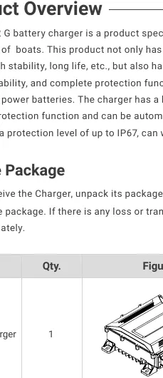
Comprehensive user guide for the ePropulsion G Battery Charger 16A (Model HK-MF-108-32). Includes installation instructions, electrical connection diagrams, safety precautions, and warranty information.
Quick answers from the manual
Quick answer
- The ePropulsion G Battery Charger 16A (HK-MF-108-32) is designed for charging ePropulsion G series boat batteries. It features IP67 protection, thermal overheating protection, and supports 90-265V AC input. p. 5, 7, 9
Key actions
- Mounting the charger p. 12
- Connecting cables p. 13
First start
- Ensure all cables are securely connected. Connect to AC power. The battery display lamp will cycle to indicate charging. p. 15
Technical specifications
| Parameter | Value | Meaning | Pages |
|---|---|---|---|
| Input voltage range | AC 90~265 V | Operating voltage range | p. 7 |
| Output power | 3300W@220VAC, 1650W@110VAC | Maximum output power | p. 7 |
Where to find it in the PDF
- Product Overview p. 5
- Mechanical Installation p. 12
- Electrical Connection p. 13
Table of contents
Manual images
Click an image to enlargeQuick guide from the manual
The ePropulsion G Battery Charger 16A (Model HK-MF-108-32) is designed specifically for charging ePropulsion G series boat batteries. It features a fully sealed, IP67-rated design for use in complex environments and includes built-in thermal protection. Before use, ensure the charger is correctly mounted and all cables (power, output, and communication) are securely connected according to the provided diagrams.
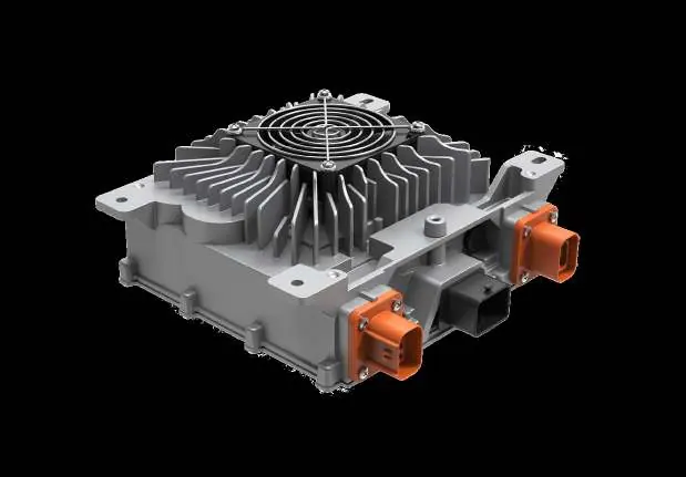
Product Overview
The charger is a high-efficiency power source for boat batteries. Key features include:
- High Protection: IP67 ingress protection class.
- Thermal Management: Built-in temperature sensor with automatic overheating protection (internal 90°C).
- Compatibility: Designed for ePropulsion G series batteries.
- Diagnostics: Supports UDS diagnosis with CAN wake-up function.
Safety Warnings
Always exercise caution when installing or operating the charger:
- Electric Shock Hazard: The equipment uses 230V AC power. Always power off before handling electrical connectors, switches, or cables.
- Burn Hazard: Surfaces may become hot during and shortly after operation. Avoid contact.
- Operational Safety: Do not plug or unplug equipment while the machine is running.
Mechanical Installation
The charger comes with mounting plates for installation:
- Ensure the charger fan is facing downward to allow for heat dissipation.
- Torque for self-tapping bolts: 6 N.m.
- Torque for bolts and nuts: 7.7 N.m.
- Use the provided punching card to locate mounting positions.
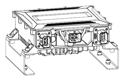
Electrical Connection
The charger requires three sets of cables:
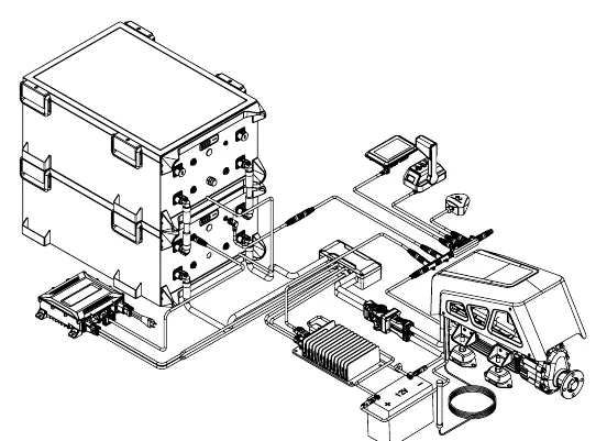
- Power Cable: Connect to a suitable plug rated for over 16A or directly to a circuit breaker. Ensure correct termination of live, neutral, and GND.
- Output Cable: Connects to the bus-bar box. Ensure positive and negative terminals are not reversed. Uses M8 bolts.
- Communication Cable: Connects the charger to the battery. For single batteries, plug into the 'CHARGER' port. For multiple batteries, connect to the 'CHARGER' port of the first battery.
Charging Precautions
- Connect the positive and negative electrodes of the charger to the battery through the bus box.
- Connect the communication line to the battery CHARGE interface.
- Connect the charger to the AC power supply.
- The battery display lamp will cycle to indicate successful charging.
- Once charging is complete, disconnect the AC power supply.
Technical Specifications
Environmental: Operation temperature -40°C to 55°C, IP67 rating.
Input: 90-265V AC, 47-63 Hz, ≤16A current.
Output: 65-161V DC, 32A max current, 3300W (at 220VAC) or 1650W (at 110VAC).
Warranty
The product includes a 24-month limited warranty from the date of delivery. G series batteries may qualify for an extended 36-month warranty upon registration on the official website. Warranty claims require proof of purchase and the original serial number. Commercial/professional use is not covered by the standard limited warranty.
Practical help
Common problems
Charger not working
Check AC power supply and ensure all cable connections are secure.
Overheating
The charger has built-in thermal protection and will automatically restore operation once the temperature drops.
Warranty claim
Contact ePropulsion Service Partners with proof of purchase and the serial number.
Before use
- Verify the charger model is HK-MF-108-32.
- Ensure the installation surface is suitable for mounting.
- Check all cables (power, output, communication) for damage.
- Confirm AC power supply is within 90-265V range.
- Ensure the charger fan has sufficient space for heat dissipation.
Specs in practice
- Input Voltage
- 90-265V AC range for global compatibility.
- Output Power
- 3300W at 220VAC; 1650W at 110VAC.
Images and diagrams
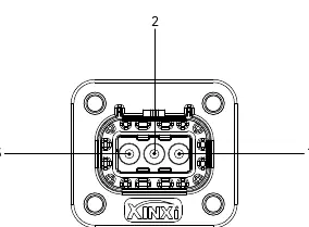
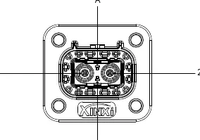
- Input connector: Pin 1 (Line), Pin 2 (Ground/PE), Pin 3 (Neutral).
- Output connector: Pin 1 (Positive), Pin 2 (Negative).
Model compatibility
- Specially designed for ePropulsion G series batteries.
- Do not use for other purposes.

Manual page author
David Miller
Documentation analyst
Organizes user manual content into clear summaries, with attention to model details, product context, and everyday usability.