Power / Batteries & Chargers
User Manual for ePropulsion E Battery Bus Bar 150A
Quick guide for the ePropulsion E Battery Bus Bar 150A. Includes installation steps, wiring diagrams, technical specifications, and safety warnings for proper power distribution.
Table of contents
Manual images
Click an image to enlargeQuick guide from the manual
The ePropulsion E Battery Bus Bar 150A is a power distribution unit designed specifically for E60 and E163 batteries. Important: The operation current must not exceed 150A. Ensure correct polarity when connecting; the positive bus bar is for the positive terminal, and the negative bus bar is for the negative terminal. Incorrect connection may cause a short circuit. Always ensure electrical connections are tightened properly.
Product Overview
Each set includes one positive and one negative bus bar. The unit is designed to facilitate the connection of battery chargers and DCDC converters to the battery system.
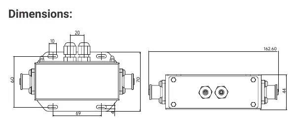
Specifications
- Maximum Current: 150A
- Inside cable connection: M5x16mm (2pcs)
- Outside cable connection: E Battery Power Cable Connector (2pcs), waterproof connector (2pcs)
In the Box
- E Battery Bus Bar Positive (1 set)
- E Battery Bus Bar Negative (1 set)
- Socket Wrench (1 pcs)
- Hexagon Cap Nuts M3 (4 pcs)
- Tapping Screw M3x10 (8 pcs)
- Ring Terminals RNB5-6-90D (6 pcs, Wire Range: 12-10 A.W.G / 4-6mm²)
- Ring Terminals RNBL1-6-90D (6 pcs, Wire Range: 12-10 A.W.G / 0.5-1.5mm²)
Installation Instructions
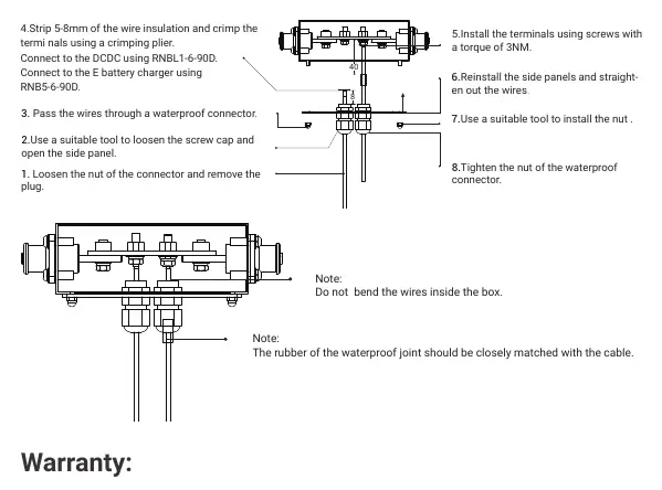
- Loosen the nut of the connector and remove the plug.
- Use a suitable tool to loosen the screw cap and open the side panel.
- Pass the wires through a waterproof connector.
- Strip 5-8mm of the wire insulation and crimp the terminals using a crimping plier. Connect to the DCDC using RNBL1-6-90D and to the E battery charger using RNB5-6-90D.
- Install the terminals using screws with a torque of 3NM.
- Reinstall the side panels and straighten out the wires.
- Use a suitable tool to install the nut.
- Tighten the nut of the waterproof connector.
Note: Do not bend the wires inside the box. The rubber of the waterproof joint should be closely matched with the cable.
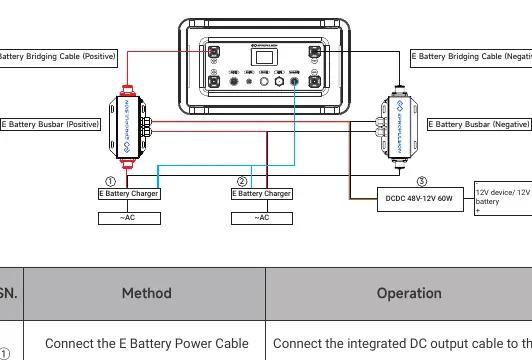
Connection Method
The system supports connections for the E Battery Power Cable, E Battery Charger, and DCDC 48V-12V 60W converter. Ensure all connections are made using the provided waterproof connectors and integrated DC output cables.
Warranty
The product is guaranteed against manufacturing defects for two years from the date of delivery. Warranty requires a legal serial number, Warranty Card, and proof of purchase from an authorized dealer. It does not cover damage from misuse, accidents, unauthorized repair, or improper storage.
Practical help
Common problems
Short circuit
Ensure the positive bus bar is connected only to the positive terminal and the negative bus bar only to the negative terminal.
Loose connections
Ensure all electrical connections are correctly tightened during installation.
Overload
The operation current must not exceed 150A.
Before use
- Verify compatibility with E60/E163 Battery.
- Gather required tools: Phillips screwdriver, 8mm hex socket, wire crimping plier, electrical tape.
- Check that the operation current will not exceed 150A.
- Ensure you have both positive and negative bus bars ready for installation.
- Verify wire insulation is stripped to 5-8mm.
Specs in practice
- Maximum Current
- 150A limit; do not exceed to prevent damage.
- Inside cable connection
- M5x16mm screws used for internal connections.
- Ring Terminals RNB5-6-90D
- Suitable for 12-10 A.W.G (4-6mm²) wire.
- Ring Terminals RNBL1-6-90D
- Suitable for 12-10 A.W.G (0.5-1.5mm²) wire.
Images and diagrams
- The connection diagram illustrates the integration of the E Battery Charger and DCDC converter with the bus bar.
- The installation diagram details the wire stripping, terminal crimping, and waterproof connector assembly process.
Model compatibility
- Specially designed for E60/E163 Battery.
- Contact ePropulsion authorized distributor before connecting third-party products.

Manual page author
David Miller
Documentation analyst
Organizes user manual content into clear summaries, with attention to model details, product context, and everyday usability.