Power / Batteries & Chargers
Technical Integration Guide for Apple MagSafe Charger Module (C222/C223)
A comprehensive technical integration guide for the Apple MagSafe Charger Module (C222/C223). This manual covers electrical requirements, pin assignments, factory configuration commands, firmware updates, and mandatory testing procedures...
Table of contents
Manual images
Click an image to enlargeQuick Guide for MagSafe Charger Module Integration
This document provides technical specifications and integration requirements for the Apple MagSafe Charger Module (models C222 and C223). It is intended for developers and manufacturers integrating this module into accessories.
Electrical Requirements
The module can be powered by an internal power supply or an external USB power source. Key electrical protections include Overvoltage (OVP), Overcurrent (OCP), Overtemperature (OTP), and Foreign Object Detection (FOD).
- Internal Power Supply: Must support 0 W to 20 W (2.22 A at 9 V). Apple recommends supporting up to 22.5 W (2.5 A at 9 V).
- External USB Power Source: Must connect via USB-C Plug and meet specific DCR (Direct Current Resistance) requirements for VBUS, GND, D+/D-, and CC lines.
- Reverse Voltage Protection: Must be integrated between the module power and ground.
Pads and Assignments
The module features 5 pads for connectivity:
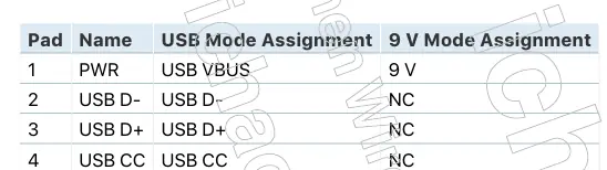
- Pad 1 (PWR): 9 V / USB VBUS
- Pad 2 (USB D-): USB D-
- Pad 3 (USB D+): USB D+
- Pad 4 (USB CC): USB CC
- Pad 5 (GND): Ground
Signals from USB D+ and D- pads must be routed as a differential pair. All pads support up to 20 AWG wires.
Factory Configuration
The module exposes a USB Virtual COM Port (VCP) for factory configuration. Commands are sent via a terminal interface using VendorSet (to set parameters) and VendorGet (to read parameters).
- Configuration Parameters: Include VendorID, ProductID, ProductPlanUID, VendorName, ProductName, ModelNumber, HardwareVersion, SerialNumber, PowerMode, and LockConfig.
- Locking Configuration: Use VendorSet LockConfig 1 to permanently lock the configuration on the next boot.
Test Procedures
Accessories must undergo specific testing to ensure compliance:
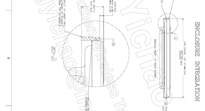
- Product Design: Verify the accessory does not scratch the device, maintains proper clearance (30 mm keep-in), and that the module surface is proud of the accessory surface.
- Power Testing: Use the MagSafe Certification Assistant app to verify battery temperature and charge test requirements.
- Low Battery Test: Ensure the device boots within 15 minutes after being drained to 0% and cooled for 30 minutes.
Manufacturer information
ESR
Practical help
Common problems
VCP not identified on Windows
Install the STM32 Virtual COM Port Driver (STSW-STM32102) and edit the stmcdc.inf file to include the specific Apple VID/PID.
Charging disabled
Ensure available power is not set to '0'. A minimum of 12 W is required to enable inductive charging.
Arcing between module and housing
Cover air gaps with non-conductive coating or insulate the metal housing near the gap with >250 µm polyurethane or >100 µm parylene.
Before use
- Verify accessory does not scratch or damage the device.
- Ensure MagSafe Charger Module surface is proud of the accessory surface using a depth probe.
- Confirm the bottom edge of the module cap is not visible.
- Verify orientation magnet surfaces are coplanar with the charger module.
- Ensure all pads are connected using up to 20 AWG wires.
Specs in practice
- LockConfig 1
- Permanently locks firmware configuration on the next boot.
Images and diagrams
- Pad Details: Shows the 5-pin layout (PWR, USB D-, USB D+, USB CC, GND) for the module.
- Enclosure Integration: Provides guidance on keep-in areas and physical mounting requirements.
Model compatibility
- Requires MagSafe-capable device running iOS 16.0 or later for testing.
- Requires USB-C power adapter supporting at least 22.5 W (2.5 A at 9 V) for testing.

Manual page author
Michael Turner
Technical manual editor
Reviews PDF manuals for structure, safety notes, and practical product details so readers can find the right information quickly.