Music / Instruments
Parts and Specifications Guide for Fender American Ultra Telecaster
A comprehensive technical guide for the Fender American Ultra Telecaster (011803XXXX). Includes detailed parts diagrams, wiring schematics, control function explanations, and technical specifications for maintenance and repair.
Table of contents
Manual images
Click an image to enlargeQuick Guide
This document serves as the official parts and specifications reference for the Fender American Ultra Telecaster (011803XXXX). It provides detailed diagrams for hardware, wiring, and control functions, which are essential for maintenance, repairs, and understanding the instrument's electronics.
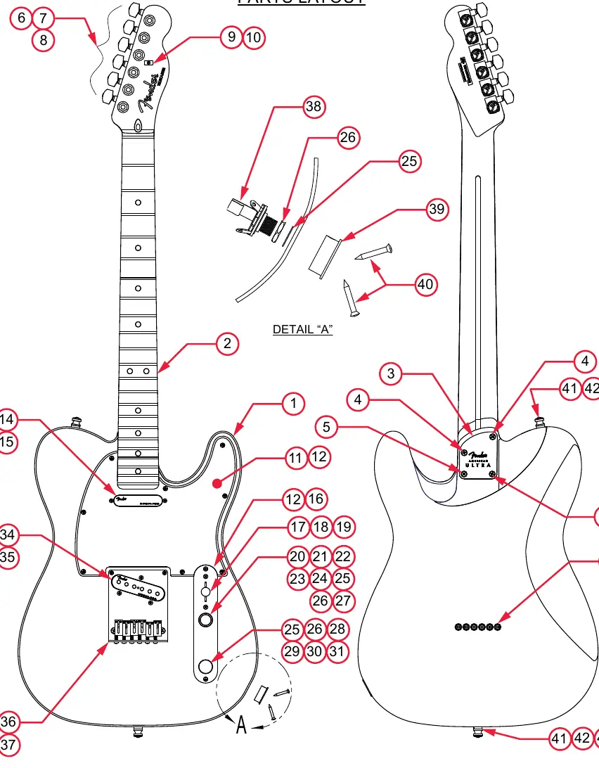
Parts Layout and List
The manual includes a comprehensive parts layout diagram and a corresponding parts list. The list details every component, including body, neck, pickguard, pickups, and hardware, along with their specific part numbers. Use these lists to identify replacement parts for your instrument.
Wiring Assembly
The wiring assembly diagram illustrates the signal path for the American Ultra Telecaster. Key components shown include:
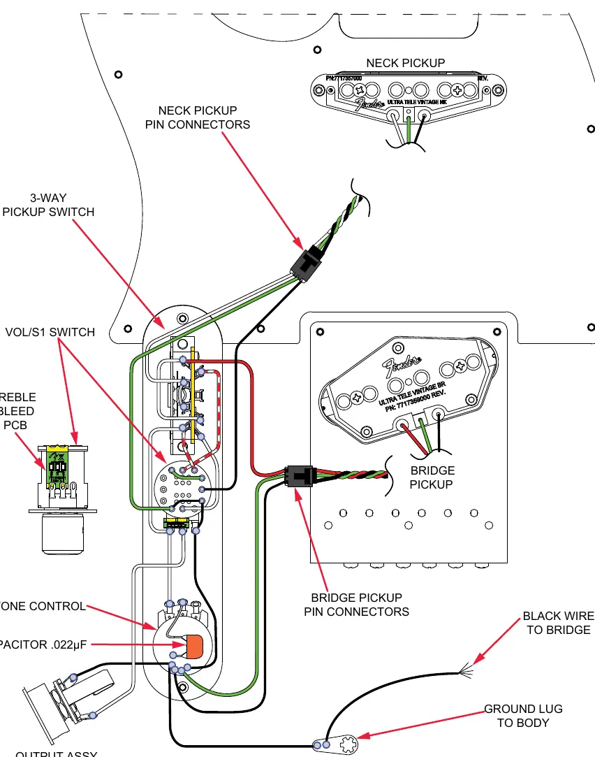
- 3-Way Pickup Switch: Manages pickup selection.
- VOL/S1 Switch: Controls master volume and pickup configuration.
- Treble Bleed PCB: Maintains high-frequency clarity when rolling off the volume.
- Grounding: Shows the ground lug connection to the body and the black wire connection to the bridge.
Switch and Control Functions
The instrument features specific control configurations:
- 3-Way Switch: Standard positions for Neck and Bridge pickup selection.
- S-1 Switch: This switch functions only when the 3-way switch is in position #2.
- Parallel vs. Series: When the S-1 switch is in the UP position, pickups are connected in parallel. When in the DOWN position, pickups are connected in series.
Technical Specifications
The manual provides precise measurements for setup and maintenance:
- Neck Profile: Ultra Modern "D" shape.
- Fret Size: Medium Jumbo.
- Pickup Specs: Both Neck and Bridge pickups use Alnico 5 unbeveled magnets with North polarity.
- Adjustments: Includes specific hex key sizes for saddle height (.050") and truss rod adjustment (1/8").
Manufacturer information
Fender Musical Instruments Corporation
Practical help
Common problems
S-1 switch does not seem to change the sound.
The S-1 switch only functions when the 3-way pickup switch is in position #2. Ensure the switch is in this position before attempting to use the S-1 feature.
Pickup replacement or wiring issues.
Refer to the Wiring Assembly diagram on page 4 to verify the correct connection of the Treble Bleed PCB and ground wires.
Before use
- Verify all hardware components using the Parts List if performing maintenance.
- Ensure you have the correct hex keys: .050" for saddle height and 1/8" for truss rod adjustment.
- Check the 3-way switch position before testing S-1 switch functionality.
- Consult the pickup specifications (DC resistance) if troubleshooting output issues.
Specs in practice
- Neck Profile
- Ultra Modern 'D' shape, providing a specific feel and thickness.
- Pickup Resistance
- Neck: 11.3-11.7kΩ; Bridge: 9.9-10.5kΩ.
Images and diagrams
- Parts Layout: Identifies all hardware components by reference number.
- Wiring Assembly: Shows the signal path, including the Treble Bleed PCB and S-1 switch.
- Switch Functions: Details the parallel/series pickup configurations based on switch position.
Model compatibility
- Parts listed are specific to the American Ultra Telecaster series.
- S-1 switch functionality is limited to position #2 of the 3-way switch.

Manual page author
Emily Carter
User documentation editor
Prepares concise manual descriptions and highlights the most useful setup, operation, and maintenance information for readers.