Tools / Measuring Tools
User Manual for FNIRSI-1013D Two Channel Plate Oscilloscope
Quick guide for the FNIRSI-1013D oscilloscope. Learn about interface navigation, touch controls, waveform measurement, troubleshooting, and specific circuit testing methods.
Table of contents
Manual images
Click an image to enlargeQuick guide from the manual
The FNIRSI-1013D is a dual-channel, flat-panel oscilloscope featuring a 7-inch 800x480 resolution display, 1GSa/s sampling rate, and 100MHz analog bandwidth. It includes a built-in 6000mAh battery and 1GB of internal storage for waveforms and screenshots. This device is designed for maintenance and R&D applications.
Important safety and usage notes
- Probe Bandwidth: The 1X probe file has a 5MHz bandwidth, while the 10X probe file has 100MHz. For signals above 5MHz, you must set the probe switch to 10X and the oscilloscope to 10X mode to avoid signal attenuation.
- Charging: Use an original 5V/2A charger. Charging via a computer USB port may be insufficient and lead to performance issues.
- Calibration: If the baseline (0V) and the left arrow (0V) do not align when there is no signal input, perform a baseline calibration via the System Settings menu.
Interface and touch controls
The device operates via a touch screen interface. Key elements include:
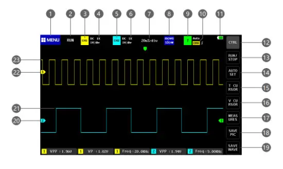
- Menu (1): Access system settings, saved waveforms, and USB mode.
- Channel Controls (3, 5): Tap to open control bars for CH1/CH2 to enable/disable channels, set coupling (AC/DC), and adjust probe magnification (1X/10X/100X).
- Time Base (7): Adjusts the horizontal scale.
- Trigger (9, 10): Configure trigger channel, mode (Auto, Single, Normal), and edge.
- Measurement (17): Select parameters to display on screen.
- Save (18, 19): Capture screenshots or save waveform data to internal storage.
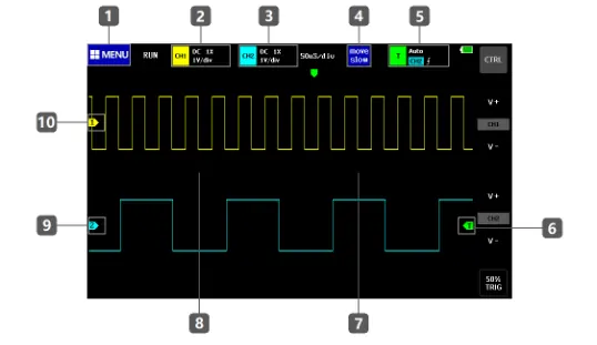
Operation instructions
To operate the oscilloscope effectively, follow these procedures:
- Adjusting Waveforms: Use the right half of the display to zoom in horizontally (reduce time base) and the left half to zoom out (increase time base). Use the CTRL button to access vertical zoom controls (V+/V-).
- Moving Waveforms: Tap the waveform area and drag to move the waveform position.
- Triggering: Use the green arrow on the right to adjust trigger voltage. For non-periodic digital signals, switch the trigger mode to Normal or Single.
- Automatic Adjustment: Press the AUTOSET button to automatically identify the signal and optimize display parameters.
Common circuit test methods
The manual provides specific guidance for various measurements:
- Battery/DC Voltage: Use 1X gear for voltages below 40V. Set to DC coupling.
- Crystal Measurement: Use 10X gear for both probe and oscilloscope to prevent oscillation stop.
- PWM/MOS/IGBT: Generally uses 1X gear. Ensure trigger mode is set to Auto.
- Mains (220V/110V): Use 100X probe and set oscilloscope to 100X. Use AC coupling.
- Automotive/Bus Signals: Use 1X gear, Normal trigger mode, and adjust time base to 20uS.
Manufacturer information
Shenzhen FNIRSI Technology Co., Ltd.
Practical help
Common problems
Device won't turn on after receiving
The battery may be depleted. Charge using a 5V/2A charger for at least 30 minutes. Do not use a computer USB port.
No waveform displayed / only one line
Check if the system is paused. Press the AUTOSET button. Verify the probe is not short-circuited or disconnected.
Voltage or frequency data shows 0
Adjust vertical sensitivity and time base, or press AUTOSET to ensure a clear, complete periodic waveform is displayed.
Waveform jumps up and down
Set trigger mode to Auto. Ensure the probe is properly grounded and the probe tip is connected.
High frequency signal is attenuated
Ensure the probe switch is set to 10X and the oscilloscope input setting is also set to 10X.
Before use
- Charge the device fully using a 5V/2A charger.
- Verify the probe switch (1X/10X) matches the signal requirements.
- Perform baseline calibration if the 0V indicator is offset.
- Ensure the trigger mode is set to Auto for periodic signals.
- Check that the probe is not damaged or disconnected.
Images and diagrams
- The UI diagram (Page 3) identifies 36 touch-sensitive areas, including menu access, channel controls, time base, trigger settings, and measurement buttons.
Model compatibility
- Only use probes with a bandwidth of 100MHz or higher.
- Do not use computer USB ports for charging; use a dedicated 5V/2A charger.

Manual page author
Emily Carter
User documentation editor
Prepares concise manual descriptions and highlights the most useful setup, operation, and maintenance information for readers.