Tools / Measuring Tools
User Manual for IDEAL 61-357 and 61-347 Digital Multimeters
Quick guide and operation manual for the IDEAL 61-357 and 61-347 Digital Multimeters. Includes safety instructions, measurement procedures, maintenance, and technical specifications.
Table of contents
Manual images
Click an image to enlargeQuick guide from the manual
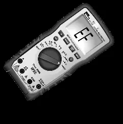
The IDEAL 61-357 and 61-347 are auto-ranging TRMS digital multimeters. Before use, always inspect the meter and test leads for damage. Ensure you are wearing appropriate PPE as per NFPA 70E standards. If the meter displays LEAd, check that your test leads are in the correct terminals. If the meter displays FUSE, the internal fuse is blown and must be replaced. The 61-357 model includes additional features like LoZ (Low Impedance) mode and an analog bar graph.
Product Description
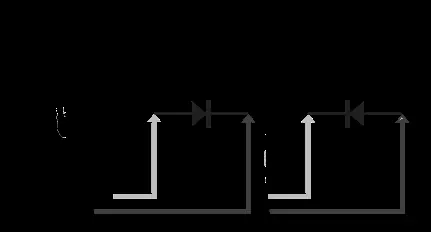
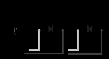
These meters measure AC/DC current, voltage, frequency, resistance, continuity, capacitance, and diodes. Temperature is measured using a K-Type thermocouple. Both models feature a non-contact voltage (NCV) sensor located at the top center of the meter to detect live voltage between 40V and 600V AC.
Safety Information
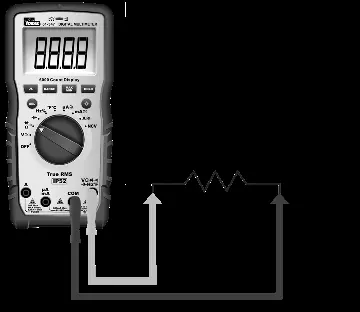
These meters are rated for CAT III 1000V and CAT IV 600V environments. Always follow safety procedures and use proper PPE. Do not use the meter if the case is cracked or if the battery door is not secured. Keep fingers behind the tactile barrier on the meter and the guard rings on the test leads during measurements. Disconnect circuit power and discharge high-voltage capacitors before measuring resistance, continuity, or capacitance.
Operating Controls
The meter features a central rotary dial for selecting measurement functions. Key controls include: HV & Continuity LED, LCD Display, Backlight Button, Function Select (SEL) Button, and Input Terminals for Volts/Ohms, COM, mA/uA, and Amps. The 61-357 model also features an analog bar graph.
Measurement Procedures
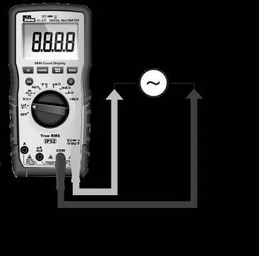
To measure, rotate the dial to the desired function. Use the SEL button to toggle between sub-functions (e.g., AC/DC, F/C, Resistance/Continuity). For voltage measurements, the 61-357 offers a LoZ setting to eliminate ghost voltages. For current measurements, ensure the test leads are in the correct terminal (A or mA/uA) to avoid the LEAd warning. Always connect the common (COM) lead before the live lead.
Maintenance and Service
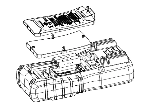
Inspect the battery compartment monthly. If the low battery indicator appears, replace the batteries immediately. To replace fuses or batteries, disconnect all test leads and power off the meter. Use only specified replacement fuses: 11A/1000V for the 10A terminal and 600mA/1000V for the mA terminal. Clean the case with a damp cloth and mild detergent; do not use abrasives or solvents.
Technical Specifications
The meters feature a 6000-count LCD display and are IP52 dust and water-resistant. Operating temperature ranges from 32°F to 122°F (0°C to 50°C) depending on humidity levels. Power is supplied by 3 x 1.5V AAA batteries with a typical life of 100 hours.
Practical help
Common problems
Meter displays 'LEAd' and beeps
Test leads are inserted into the wrong input terminal for the selected function. Move leads to the correct terminal.
Meter displays 'FUSE' and beeps
The internal fuse is blown. Replace with the specified fuse (11A/1000V or 600mA/1000V).
Low battery indicator appears
Replace batteries immediately to ensure measurement accuracy.
Ghost or stray voltage readings
Use the LoZ (Low Impedance) setting on the 61-357 model to eliminate induced voltages.
Before use
- Visually inspect the meter case for cracks or damage.
- Check test leads for damaged insulation, exposed metal, or bent probes.
- Verify batteries are correctly installed and the battery door is secured.
- Ensure you are wearing appropriate PPE as per NFPA 70E.
- Confirm the meter is set to the correct function and range for the task.
Specs in practice
- CAT III 1000V / CAT IV 600V
- Safety ratings indicating the meter's ability to withstand voltage transients in specific electrical environments.
- LoZ (61-357 only)
- Low impedance mode used to drain ghost or stray voltages from circuits.
Images and diagrams
- The rotary dial selects the primary measurement mode (Voltage, Current, Resistance, etc.).
- Input terminals are clearly labeled for specific measurements (A, mA/uA, COM, V/Ohms).
- The NCV sensing point is located at the top center of the meter.
Model compatibility
- The 61-357 model includes LoZ and an Analog Bar Graph, which are not available on the 61-347 model.

Manual page author
Michael Turner
Technical manual editor
Reviews PDF manuals for structure, safety notes, and practical product details so readers can find the right information quickly.