Tools / Measuring Tools
Technical Manual for IDEAL 61-773 and 61-775 Clamp Meter
Technical manual for IDEAL 61-773 and 61-775 clamp meters. Includes safety precautions, specifications, performance verification, calibration procedures, and battery replacement.
Table of contents
Manual images
Click an image to enlargeQuick Guide from the Manual
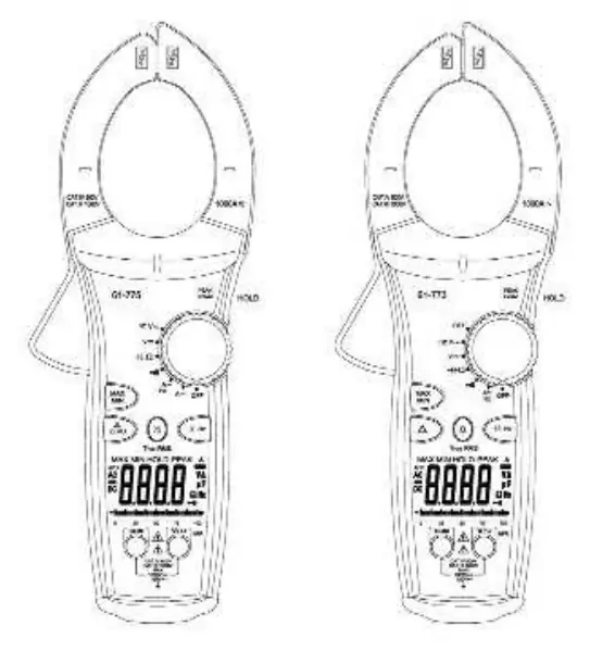
This technical manual provides service information for the IDEAL 61-773 and 61-775 TightSight clamp meters. It is intended for qualified personnel only. Key procedures include performance verification, annual calibration, and battery replacement.
Safety Information
Warning: To avoid shock or injury, do not perform verification tests or calibration procedures unless qualified. The 61-770 series contains static-sensitive parts; follow standard handling practices.
- High Voltage Warning (HI-V): The meter beeps and lights an LED when >30V AC/DC is present through test leads. This feature does not work through the clamp head.
- Specific Precautions: Do not operate without covers. Never apply voltage outside the specified range. Do not connect/disconnect probes while connected to a voltage source. Do not operate in wet or damp conditions.
Specifications
The meters feature a 4-digit LCD (9999 count) with a sampling rate of 2.0 times/second. They are powered by a 9V battery (NEDA 1604) with approximately 100 hours of typical alkaline battery life.
- Maximum Cable Size: 2.0" (51mm).
- Operating Environment: 0°C to 50°C (32°F to 122°F), 0-70% RH.
- Overload Protection: AC/DC Voltage up to 1000V DC or 750V AC RMS; Current up to 1000A.
Performance Verification
If the meter does not conform to the limits listed in the manual's tables (Tables 1-7), calibration is required. Before testing, ensure the calibrator has warmed up for 30 minutes and the meter battery measures at least 7.5V DC.
Calibration Procedure
It is recommended that all IDEAL meters undergo calibration annually. The procedure involves:
- Auto Calibration: Set the short circuit 2-pin connector on the PC board from J2 to J1 position.
- Function Calibration: Perform individual calibration for V AC, V DC, Continuity, Resistance, Capacitance, and A DC/AC (61-775 only) as needed.
- Adjustment: Use the MAX/MIN button to adjust readings until they match the calibrator output within specified tolerances.
- Finalization: Return the 2-pin connector to the J2 position and replace the case bottom.
Battery Replacement
To replace the battery:
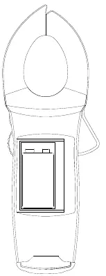
- Disconnect test leads and turn the meter off.
- Use a Phillips head screwdriver to remove the screws on the battery cover.
- Remove the old battery and install a new 9V battery (NEDA #1604), ensuring proper polarity.
- Reinstall the battery cover.
Practical help
Common problems
Meter beeps and LED lights up
Indicates >30V AC/DC voltage is present through test leads. This is a safety feature.
Display shows 'OL'
This is the over-range indication.
Low battery indicator appears
Replace the 9V battery immediately.
Inaccurate readings
Perform the performance verification procedure; if it fails, the meter requires calibration.
Before use
- Ensure battery voltage is at least 7.5V DC.
- Verify all covers are securely in place.
- Check that test leads are not damaged.
- Ensure the environment is not wet or damp.
- Confirm the function switch is set to the correct range.
Specs in practice
- TightSight Display
- Designed for viewing current measurements in tight locations; displays numerical values for other functions.
- CAT III / CAT IV
- Safety ratings indicating the meter's suitability for distribution level mains (CAT III) and service entrance (CAT IV) environments.
Images and diagrams
- Figure 1: Illustrates the battery compartment location and the screws required for access.
Model compatibility
- 61-775 model supports DC Current measurement; 61-773 does not.
- Both models support True RMS sensing.

Manual page author
Michael Turner
Technical manual editor
Reviews PDF manuals for structure, safety notes, and practical product details so readers can find the right information quickly.