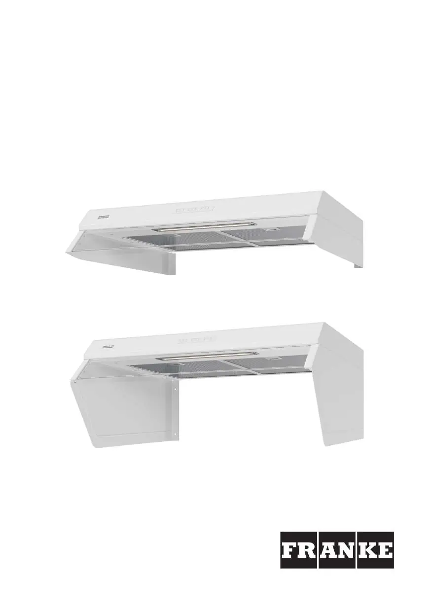
Home Appliances / Range Hoods
User Manual for Franke 1220B-16 Cooker Hood
Quick guide for the Franke 1220B-16 cooker hood. Includes installation steps, electrical connection, damper adjustment, filter cleaning, and troubleshooting.
Table of contents
Manual images
Click an image to enlargeQuick guide from the manual
This document provides essential instructions for the Franke 1220B-16 cooker hood. Key safety requirements include maintaining a minimum distance of 44 cm from electric hobs and 65 cm from gas hobs. Installation and electrical work must be performed by a qualified professional. The hood features a filter guard and adjustable damper for air flow control.
Safety Instructions
- Installation: Must be carried out by a qualified professional.
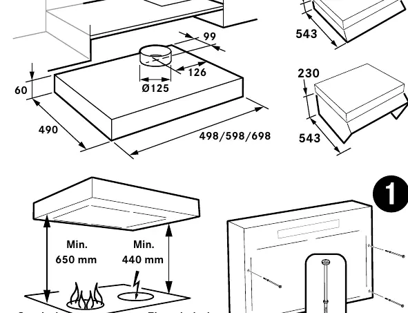
- Distances: Minimum 44 cm from electric hobs; 65 cm from gas hobs.
- Ventilation: Ensure adequate air supply if using the hood simultaneously with other energy-consuming appliances (gas, wood, oil stoves).
- Maintenance: Disconnect from power before cleaning. Clean filters regularly to prevent fire hazards.
- Prohibitions: Do not flambé food underneath the hood.
Functions and Operation
The control panel features buttons A through F:
- A: Lighting.
- B: Increased general and sanitary ventilation (runs at top speed, returns to basic after 60 minutes).
- C, D, E: Open damper and set fan speed (1, 2, or 3).
- F: Timer extension (+30 minutes) or Filter guard reset.
Programming: To activate/deactivate functions (like the filter guard), press and hold buttons A and B for 3 seconds until they flash 3 times. Select the function, then save by holding A and B for 3 seconds until they flash twice.
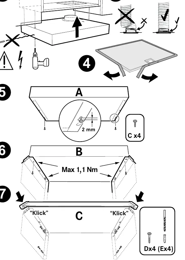
Installation
The hood is designed for mounting above a hob. Ensure the installation complies with local building regulations. The unit requires a 230 V electrical connection. The junction box or wall socket must remain accessible after installation.
Adjusting Air Flow
Damper adjustment and speed changes must be performed by a qualified professional. The basic ventilation is set by moving the sliding damper, which becomes accessible after removing the grease filter. The transformer voltage for the lowest speed can be adjusted to 80 V via reprogramming.
Care and Maintenance
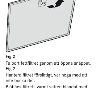
- Grease Filter: Remove by opening the snap retainer. Clean at least every two months (more often with intensive use) using warm water and washing-up liquid, or in a dishwasher.
- General Cleaning: Clean the inside of the hood and the damper at least twice a year with a damp cloth and washing-up liquid.
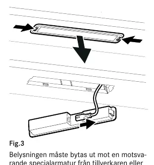
- LED Lighting: If the lighting fails, it must be replaced with an equivalent special light fixture from the manufacturer or service agent.
Troubleshooting
If the unit is not working:
- Check that the fuse is intact.
- Disconnect the power supply, wait, and switch it on again.
- Ensure the connector is not bent or twisted.
- If the product has a stove alarm or stove guard, refer to the separate instructions provided with that specific accessory.
Practical help
Common problems
Product not working
Check the fuse, disconnect and reconnect the power supply, and ensure the connector is not bent or twisted.
Filter needs cleaning
If the filter guard is activated, the LED on button F will flash when it is time to clean the filter.
Before use
- Ensure a minimum distance of 44 cm (440 mm) from electric hobs.
- Ensure a minimum distance of 65 cm (650 mm) from gas hobs.
- Verify that the electrical connection is 230 V~.
- Ensure the installation is performed by a qualified professional.
- Check that the junction box or wall socket is accessible after installation.
Specs in practice
- LED Lighting
- 6.5W power consumption.
- Connection Power
- Max 300W at 230V.
- Transformer Output
- Adjustable voltages: 60, 80, 100, 130, 145, and 180 V.
Images and diagrams
- Fig 1: Control panel layout with buttons A-F.
- Fig 2: Grease filter removal using the snap retainer.
- Fig 3: LED lighting replacement procedure.
- Fig 4: Product label location (left side under filter/bottom plate).
Model compatibility
- Not for use over gas hobs if the product is equipped with a stove alarm or stove guard (see separate instructions).

Manual page author
David Miller
Documentation analyst
Organizes user manual content into clear summaries, with attention to model details, product context, and everyday usability.