Electronics / Networking
User Manual for FS 10GBASE-ZR SFP+ Transceiver
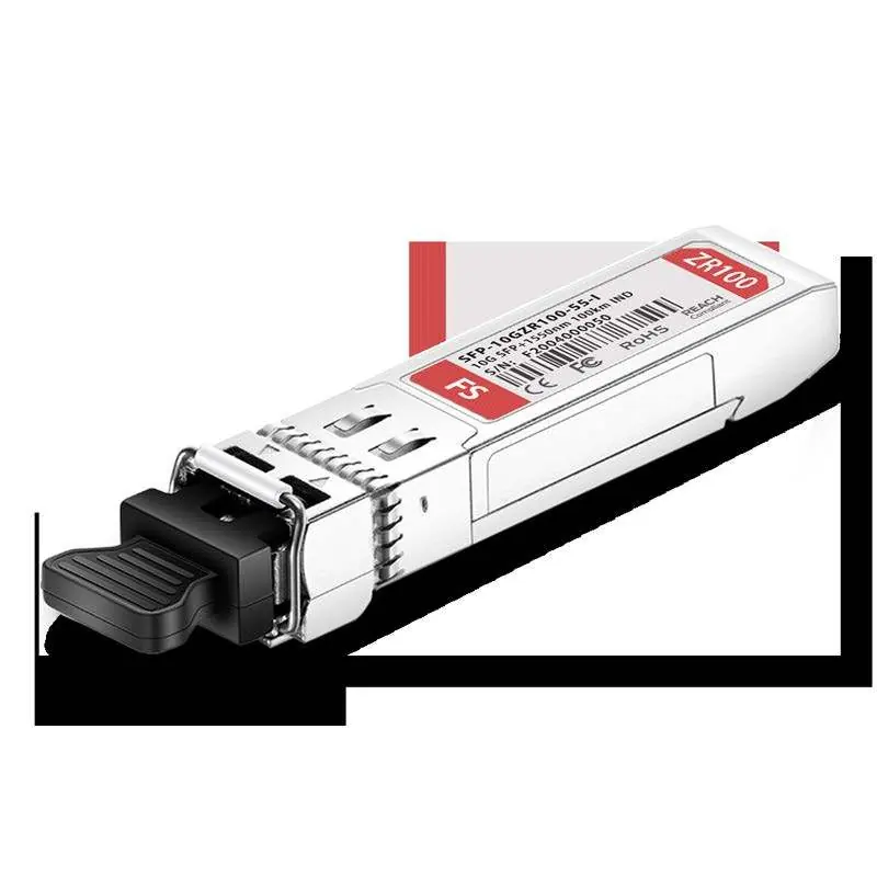
Quick guide for the FS 10GBASE-ZR SFP+ 1550nm 100km Industrial DOM Duplex LC Transceiver. Includes pin definitions, electrical and optical specifications, and mechanical dimensions.
Table of contents
Manual images
Click an image to enlargeQuick guide from the manual
This document provides technical specifications and operational guidelines for the FS 10GBASE-ZR SFP+ 1550nm 100km Industrial Transceiver. This module is designed for high-speed data links up to 11.3Gb/s and is compliant with SFP+ MSA and IEEE 802.3ae standards. It is suitable for harsh industrial environments with an operating temperature range of -40°C to 85°C.
Operating conditions
Ensure the module is operated within the following recommended parameters to prevent damage and ensure performance:
- Power Supply Voltage: 3.135V to 3.465V (Typical 3.3V).
- Operating Case Temperature: -40°C to 85°C.
- Data Rate: 10.3125 Gb/s.
- Relative Humidity: 5% to 95% (Non-condensation).
- Damage Threshold: 0 dBm.
Optical characteristics
The transceiver utilizes a 1550nm EML transmitter and APD receiver. Key optical performance metrics include:
- Link Distance: Up to 100km on 9/125µm Single Mode Fiber (SMF).
- Transmitter Center Wavelength: 1530nm to 1565nm.
- Average Optical Power: 1 dBm to 5 dBm.
- Receiver Sensitivity: -25 dBm.
- Input Saturation Power (Overload): -8 dBm.
Pin definitions
The module features a 20-pin connector interface. Key pins include:
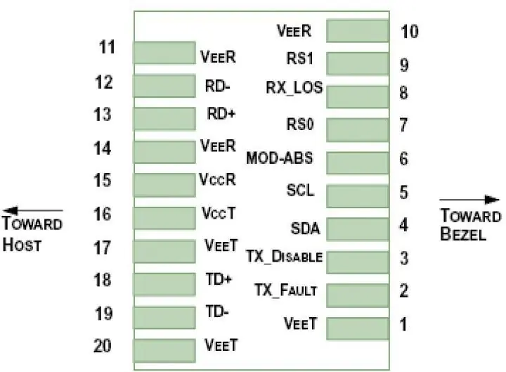
- VEE T / VEE R: Transmitter and Receiver Ground.
- TFAULT: Transmitter Fault indication (High output indicates fault).
- TDis: Transmitter Disable (Laser output disabled on High or Open).
- SDA / SCL: 2-Wire Serial Interface Data and Clock lines.
- MOD_ABS: Module Absent (Grounded within the module).
- LOS: Loss of Signal Indication (Logic 0 indicates normal operation).
- RD+/RD-: Receiver Non-inverted/Inverted Data Out.
- TD+/TD-: Transmitter Non-inverted/Inverted Data In.
Digital diagnostic specifications
The module supports Digital Diagnostic Monitoring (DOM) compliant with SFF-8472 Rev10.2. It monitors temperature, supply voltage, RX power, bias current, and TX power with specific absolute error tolerances defined for the operating range.
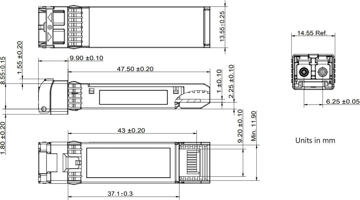
Mechanical specifications
The module is designed with an SFP+ footprint. Refer to the mechanical outline diagram for precise dimensions in millimeters, including the 14.55mm reference width and 6.25mm spacing for the optical interface.
Manufacturer information
FS.com
Practical help
Common problems
Transmitter Fault (TFAULT)
A high output on the TFAULT pin indicates a fault caused by either the TX bias current or the TX output power exceeding preset alarm thresholds.
Loss of Signal (LOS)
Logic 1 on the LOS pin indicates that no signal is detected. Ensure fiber connections are secure and within the 100km link distance.
Module Not Detected
Check the MOD_ABS pin. It should be pulled low to indicate the module is properly plugged into the host device.
Before use
- Verify host device compatibility with SFP+ MSA and IEEE 802.3ae standards.
- Ensure the power supply is stable at 3.3V.
- Use 9/125µm Single Mode Fiber (SMF) for the 100km link.
- Confirm the operating environment temperature is between -40°C and 85°C.
- Ensure the host board has appropriate pull-up resistors (4.7kΩ-10kΩ) for TFAULT, MOD_ABS, and LOS pins.
Specs in practice
- Power Consumption
- Less than 2W, ensuring efficient operation.
- Operating Temperature
- -40°C to 85°C, suitable for industrial and outdoor applications.
Images and diagrams
- Pin Definitions: Illustrates the 20-pin layout for the host board connector, identifying ground, data, and control pins.
- Mechanical Outline: Provides the physical dimensions of the transceiver module in millimeters.
Model compatibility
- Compliant with SFP+ MSA and IEEE 802.3ae standards.
- Tested for compatibility with over 200 vendors, including Cisco, Brocade, Dell, and Huawei.

Manual page author
Michael Turner
Technical manual editor
Reviews PDF manuals for structure, safety notes, and practical product details so readers can find the right information quickly.