Electronics / Networking
User Manual for QSFPTEK 10GBASE-T SFP+ Copper Transceiver
Quick guide for the QSFPTEK 10GBASE-T SFP+ Copper Transceiver (QT-SFP-10G-T). Includes pin assignments, electrical pad layout, mechanical specifications, and operating parameters.
Table of contents
Manual images
Click an image to enlargeQuick guide from the manual
The QSFPTEK QT-SFP-10G-T is a high-performance integrated duplex data link module designed for bi-directional communication over copper cable. It is specifically engineered for high-speed communication links requiring 10 Gigabit Ethernet over Cat 6a/7 cabling. This module is the first SFP+ transceiver to offer 10Gb/s communication over this type of media.
Features
- Supports links up to 30m using Cat 6a/7 cable.
- SFF-8431 and SFF-8432 MSA compliant.
- IEEE 802.3az compliant.
- Low power consumption (2.5W max @ 30m).
- Fast Retrain EMI Cancellation Algorithm.
- Low EMI emissions.
- I2C 2-wire serial interface for Serial ID and PHY registers.
- Auto-negotiates with other 10GBase-T-NC PHYs.
- Automatic detection and correction of wiring and polarity swaps.
- Robust die-cast housing with a bail latch style ejector mechanism.
- Supports both unshielded and shielded cables.
General Specifications
The module operates within the following parameters:
- Bit Error Rate (BER): 10^-12
- Operating Temperature: -5°C to 85°C (Case temperature)
- Storage Temperature: -40°C to 85°C (Ambient temperature)
- Operating Humidity: 5% to 95% (Non-condensing)
- Power Consumption: 2.3W to 2.5W @ 30m
- Input Voltage: 3.0V to 3.6V
Pin Assignment
The module features a 20-pin interface. Key pins include:
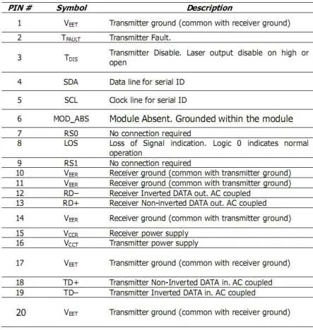
- Pins 1, 10, 11, 14, 17, 20: Transmitter/Receiver ground.
- Pin 2: Transmitter Fault.
- Pin 3: Transmitter Disable (Laser output disable on high or open).
- Pin 4: SDA (Data line for serial ID).
- Pin 5: SCL (Clock line for serial ID).
- Pin 6: Module Absent (Grounded within the module).
- Pin 8: Loss of Signal (LOS) indication.
- Pins 12, 13: Receiver Data (Inverted/Non-inverted).
- Pins 18, 19: Transmitter Data (Non-inverted/Inverted).
- Pins 15, 16: Receiver/Transmitter power supply.
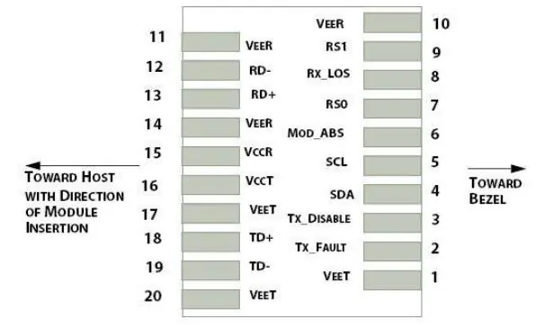
Electrical Pad Layout
The electrical pad layout defines the physical connection points for the module when inserted into the host device. Ensure proper orientation toward the host and bezel as indicated in the technical diagrams.
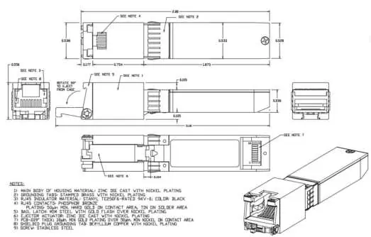
Mechanical Specifications
The module is constructed with a zinc die-cast housing with nickel plating. It utilizes a bail latch ejector mechanism for easy removal from the cage. Refer to the mechanical dimensions diagram for precise physical measurements.
Ordering Information
- QT-SFP-10G-T: Copper SFP, 10.125 Gb/s, RJ-45 connector, 30M, 0°C to +70°C.
- QT-SFP-M: Copper SFP, 1000M, RJ-45 connector, 100M, 0°C to +70°C.
- QT-SFP-T: Copper SFP, 10/100/1000M, RJ-45 connector, 100M, 0°C to +70°C.
Manufacturer information
QSFPTEK
Practical help
Common problems
Link failure or connection issues
Verify that the cable used is Cat 6a or Cat 7 and that the total length does not exceed 30 meters.
Module not detected
Ensure the module is fully inserted into the SFP+ port and that the host device supports 10GBASE-T SFP+ modules.
Before use
- Verify the host device SFP+ port supports 10GBASE-T.
- Ensure the network cable is Cat 6a or Cat 7.
- Confirm the cable length is within the 30-meter limit.
- Check that the operating environment temperature is between 0°C and 70°C.
Specs in practice
- SFF-8431/8432
- Industry standards for SFP+ pluggable modules.
Images and diagrams
- Pin Assignment: Details the 20-pin interface configuration for power, ground, and data transmission.
- Electrical Pad Layout: Illustrates the physical arrangement of pads for host insertion.
- Mechanical Dimensions: Provides the physical size and housing details of the transceiver.
Model compatibility
- Supports both unshielded and shielded cables.
- Compliant with IEEE 802.3az standard.
- Compatible with 10GBase-T-NC PHYs.

Manual page author
Emily Carter
User documentation editor
Prepares concise manual descriptions and highlights the most useful setup, operation, and maintenance information for readers.