Electronics / Networking
User Manual for FS SFP1G-LX-31 1000BASE-LX Transceiver
Quick guide for the FS 1000BASE-LX SFP 1310nm 20km DOM Transceiver. Includes technical specifications, pinout descriptions, operating conditions, and compatibility information.
Table of contents
Manual images
Click an image to enlargeQuick guide from the manual
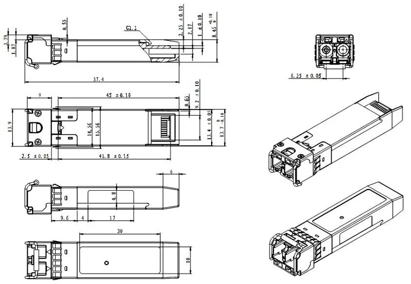
The FS 1000BASE-LX SFP transceiver (model SFP1G-LX-31) is a hot-pluggable, small form factor module designed for bi-directional serial optical data communications. It supports Gigabit Ethernet, Fiber Channel, and other optical links over single-mode fiber. This guide provides essential technical data, pinout configurations, and operating parameters.
Product Description
This module operates at a nominal wavelength of 1310nm and is compliant with the SFF-8472 SFP Multi-source Agreement (MSA). It features a 20-pin connector for hot-plug capability and includes built-in digital diagnostic functions for optical power monitoring.
Technical Specifications
General Characteristics:
- Bit Rate: 1.25 Gb/s
- Max Link Length: 20 km (using 9/125 µm SMF)
- Supply Voltage: 3.3V (3.15V - 3.45V)
- Operating Temperature Ranges: Commercial (0°C to 70°C), Extended (-5°C to 85°C), Industrial (-40°C to 85°C)
Transmitter & Receiver:
- Laser Safety: Class 1 FDA and IEC60825-1 compliant
- Receiver Sensitivity: -23 dBm
- Receiver Overload: -3 dBm
Pin Description
The module uses a 20-pin interface. Key pins include:
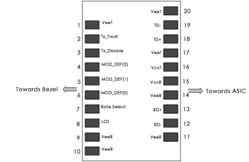
- TX Fault (Pin 2): Transmitter Fault Indication.
- TX Disable (Pin 3): Transmitter Disable input.
- MOD-DEF 0, 1, 2 (Pins 4-6): Module definition pins for serial ID and clock/data lines.
- LOS (Pin 8): Loss of Signal output.
- VccR/VccT (Pins 15, 16): Receiver and Transmitter power supplies (3.3V).
- TD+/TD- (Pins 18, 19): Differential transmitter inputs.
- RD+/RD- (Pins 13, 12): Differential receiver outputs.
Compatibility & Testing
Each transceiver is tested in the FS Assured Program to ensure compatibility with over 200 vendors, including Cisco, Brocade, Dell, and Huawei. Performance testing includes TX/RX signal quality (eye pattern, jitter), reliability (thermal shock), and protocol testing.
Manufacturer information
FS.com
Practical help
Common problems
Laser fault indication
Check if the TX Fault pin is high. This indicates a laser fault. Normal operation is indicated by a low state.
Loss of Signal (LOS)
If the LOS pin is high, the received optical power is below the worst-case receiver sensitivity. Ensure fiber connections are secure and clean.
Module not detected
Ensure Mod-Def 0 is grounded within the module and the host board pulls up the Mod-Def pins correctly.
Before use
- Verify the host device SFP slot supports 1000BASE-LX.
- Ensure the fiber cable is 9/125 µm single-mode fiber (SMF).
- Confirm the host board provides a stable 3.3V power supply.
- Check that the operating environment temperature is within the module's rated range.
- Ensure proper termination (100Ω differential) for RD and TD lines on the host board.
Specs in practice
- Max Link Length
- The maximum distance the signal can travel over 9/125 µm SMF, which is 20 km.
- Supply Voltage
- The required power input, standard 3.3V.
Images and diagrams
- The pinout diagram illustrates the 20-pin SFP interface layout, distinguishing between the Bezel side and the ASIC side.
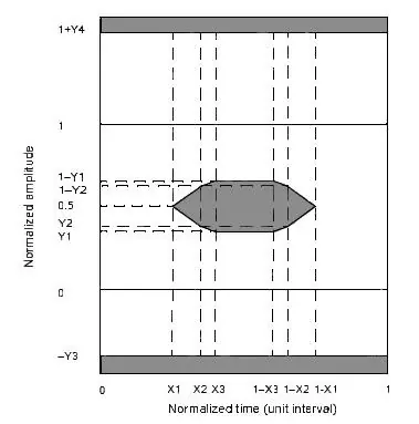
- The LOS Hysteresis diagram shows the relationship between received optical power levels and the assertion/de-assertion of the Loss of Signal status.
Model compatibility
- Compatible with Gigabit Ethernet, Fiber Channel, and SDH/SONET protocols.
- Tested for compatibility with major network equipment vendors including Cisco, Brocade, Dell, and Huawei.

Manual page author
Michael Turner
Technical manual editor
Reviews PDF manuals for structure, safety notes, and practical product details so readers can find the right information quickly.