Smart Home / Smart Relays
User Manual for GIRA 2473 00 RTC 24 V Room Temperature Controller
Quick guide for the GIRA 2473 00 RTC 24 V room temperature controller. Includes installation instructions, wiring diagrams, operating modes, and technical specifications.
Table of contents
Manual images
Click an image to enlargeQuick Guide
The GIRA 2473 00 is an electronic room temperature controller designed for 24 V AC systems. It features manual temperature setting, ECO mode for energy saving, cooling mode, and frost protection. Installation must be performed by an electrically skilled person. The device supports both pulse width modulation (PWM) and two-point control methods.
Safety Instructions
- Installation and connection must be performed by electrically skilled persons only.
- Risk of electric shock: Comply with regulations and standards for SELV circuits during installation and cable routing.
- The temperature sensor must not be painted over or become dirty during renovation work.
Device Components
The device consists of the following main parts:
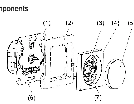
- Room temperature controller insert
- Cover frame
- Status LED
- Central plate
- Control knob
- Internal temperature sensor
- Adjustment rings for temperature limit
Intended Use
- Control of electrothermal valve drives for AC 24 V.
- Regulation of room temperature in closed rooms.
- Mounting in appliance boxes according to DIN 49073.
Functional Description
Lowering mode (ECO): By connecting the input terminal to 24 V (controlled by a central clock), the temperature is reduced by 4 °C.
Cooling mode: Can be activated via the control knob or by wiring the input terminal C with 24 V.
Temperature drop detection: If a sharp temperature drop is detected (e.g., open window), the system regulates to 5 °C for up to 30 minutes.
Offset: Allows adjustment of the control knob position to match the actual room temperature (up to +/- 3 °C).
Operation
Changing room temperature: Turn the control knob to the right or left. The LED lights up for up to 2 minutes in the color of the current mode (Red=Heating, Blue=Cooling, Orange=Frost protection).
Switching off: Press the control knob for longer than 2 seconds until the LED lights up orange. The device switches to frost protection mode.
Manual switching between heating and cooling: Press the control knob for longer than 4 seconds until the LED flashes. Briefly press again to change the mode, then press for longer than one second to save.
Installation
Selecting location: Recommended height is 1.50 m on interior walls. Avoid mounting near heat sources (ovens, direct sunlight), draughts, or behind curtains/shelf walls.
Connecting: Connect the electrothermal valve drive to the insert. Optionally connect the lowering mode input or cooling input. Ensure terminals are at the bottom when fitting into the appliance box.
Commissioning
Setting control mode and valve type: Default is PWM control and NC valve type. To change, press the control knob for longer than 20 seconds. The LED flashes green for PWM or green/blue for 2-point control. Briefly press to change, press longer than one second to save.
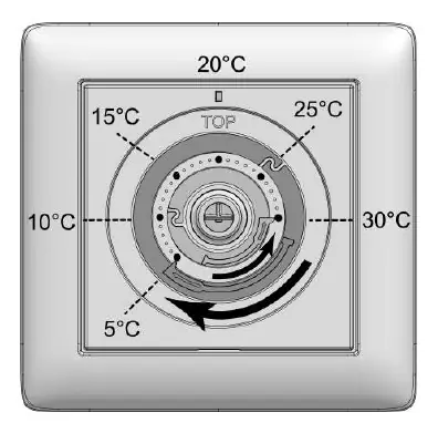
Setting temperature limits: Pull off the control knob to access the adjustment rings. Use the blue ring for minimum temperature and the red ring for maximum temperature.
Technical Data
- Rated voltage: AC 24 V SELV (± 10%)
- Mains frequency: 50 / 60 Hz
- Connected load: Max. 24 W
- Number of valve drives: 1 to 5
- Ambient temperature: -5 to +45 °C
- Controller class: IV
Practical help
Common problems
LED flashes red for 5 seconds during offset adjustment
The change was greater than +/- 3 °C and the adaptation was discarded.
Manual switching to heating mode is not possible
Check if 24 V is present at input terminal C; if so, manual switching is disabled.
Temperature reading is inaccurate
Ensure the device is not mounted near heat sources, draughts, or in direct sunlight.
Before use
- Ensure installation is performed by an electrically skilled person.
- Verify the power supply is 24 V AC.
- Check that the appliance box dimensions comply with DIN 49073.
- Ensure the temperature sensor is clean and not painted over.
Specs in practice
- Rated voltage
- AC 24 V SELV (± 10%)
- Connected load
- Max. 24 W
- Number of valve drives
- 1 to 5
- Controller class
- IV (2% contribution to energy efficiency)
Images and diagrams
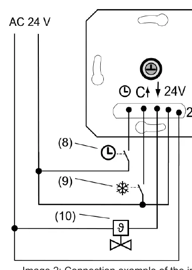
- Connection example: Shows how to connect the electrothermal valve drive, central clock for ECO mode, and heating system for cooling mode.
- Adjustment rings: Shows how to set the minimum and maximum temperature limits.
Model compatibility
- Compatible with electrothermal valve drives (NC or NO).
- Requires 24 V AC power supply.

Manual page author
David Miller
Documentation analyst
Organizes user manual content into clear summaries, with attention to model details, product context, and everyday usability.