Industrial / Pumps & Motors
Installation and operating instructions for Grundfos SEG grinder pump
Comprehensive installation and operating guide for the Grundfos SEG grinder pump. Includes detailed wiring diagrams, installation methods (auto-coupling and free-standing), maintenance procedures, and troubleshooting steps.
Table of contents
Manual images
Click an image to enlargeQuick guide from the manual
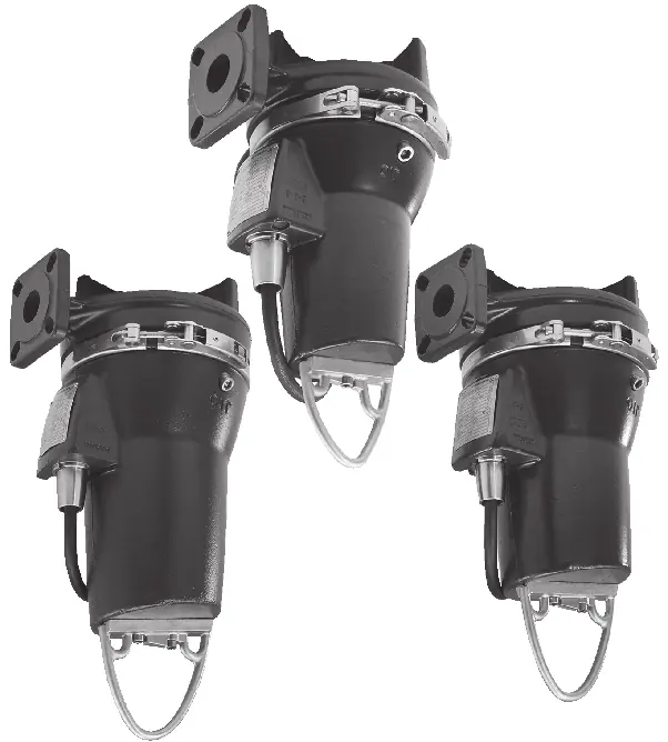
The Grundfos SEG is a submersible grinder pump designed for pumping wastewater and sewage. This manual covers installation, electrical connection, operation, and maintenance. Always ensure the pump is installed by qualified personnel and that all safety regulations are followed.
Safety instructions
Warning: Before starting any work on the pump, ensure the power supply is switched off and cannot be accidentally switched on. All electrical connections must comply with local regulations. The pump must not run dry.
Installation
The pump can be installed in two main ways:
- Auto-coupling system: Allows for easy maintenance by enabling the pump to be lifted out of the pit without disconnecting the discharge pipe.
- Free-standing installation: The pump stands on the bottom of the pit.
Ensure the pit is clean and the pump is installed vertically. For auto-coupling, ensure the guide rails are correctly aligned and the pump is securely connected to the base.
Electrical connection
Electrical connections must be performed by a qualified electrician. The pump must be connected to an external main switch with a minimum contact gap of 3 mm in all poles. Ensure the motor protection relay is set to the rated current specified on the nameplate.
Start-up
Before starting the pump:
- Check the oil level in the oil chamber.
- Verify the rotation direction.
- Ensure the pump is not running dry.
- Check that all safety devices are correctly connected.
Maintenance and service
Regular maintenance is essential for the longevity of the pump:
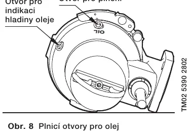
- Oil change: Change the oil every 3000 operating hours or at least once a year. Use Shell Ondina 917 oil.
- Grinder mechanism: Regularly check the grinder head and impeller for wear or blockages.
- Cleaning: Keep the pump housing and components clean.
Troubleshooting
If the pump fails to operate correctly, check the following:
- Motor does not start: Check power supply, fuses, and ensure the grinder mechanism is not blocked.
- Pump runs but stops: Check motor protection relay settings and voltage levels.
- Pump runs but does not pump liquid: Check for blockages in the discharge valve or air in the pump.
Technical data
The pump is designed for a maximum liquid temperature of 40°C. It is suitable for stationary installation and can be operated continuously if fully submerged.
Practical help
Common problems
Motor does not start
Check power supply, fuses, and ensure the grinder mechanism is not mechanically blocked.
Motor protection trips
Check motor protection relay settings and ensure voltage is within tolerance (-10%/+6%).
Pump runs but does not pump liquid
Check if the discharge valve is closed or blocked, or if there is air in the pump.
Before use
- Check oil level in the oil chamber.
- Verify rotation direction.
- Ensure the pump is not running dry.
- Check electrical connections against wiring diagrams.
- Ensure the pit is clean and free of debris.
Specs in practice
- Max. liquid temperature
- The maximum temperature of the pumped medium, which is 40°C.
Images and diagrams
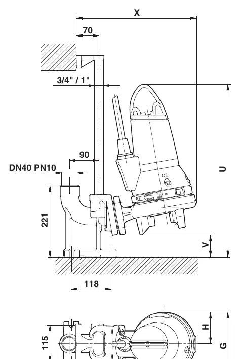
- Fig. A: Installation with auto-coupling system.
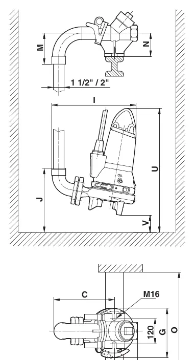
- Fig. B: Installation with hookup auto-coupling.
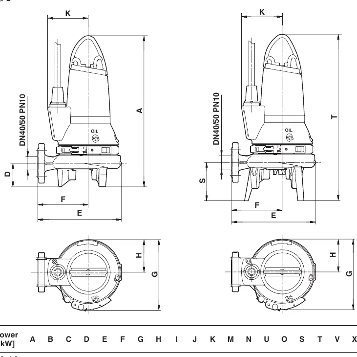
- Fig. C: Free-standing installation.
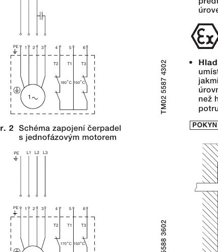
- Wiring Diagrams: Connections for 1-phase and 3-phase motors.
Model compatibility
- Suitable for sewage and wastewater.
- Not for use in potentially explosive atmospheres unless specifically rated (ATEX).
- Requires external main switch with 3mm contact gap.

Manual page author
Michael Turner
Technical manual editor
Reviews PDF manuals for structure, safety notes, and practical product details so readers can find the right information quickly.