Automotive / Motorcycle Accessories
User Manual for Vevor Single-Phase Induction Motor
Quick guide for Vevor single-phase induction motors. Includes wiring diagrams, technical specifications, safety precautions, and troubleshooting steps for models in the SY series.
Table of contents
Manual images
Click an image to enlargeImportant Information
This manual provides essential instructions for the installation, operation, and maintenance of Vevor single-phase induction motors. Ensure that the power supply voltage and frequency match the motor nameplate specifications before operation.
Safety Warnings and Precautions
- Grounding: The motor must be equipped with a reliable grounding device.
- Environment: Operate in a clean, dry, and well-ventilated area. Do not exceed 1000 meters above sea level or 45°C ambient temperature.
- Inspection: Before starting, ensure the shaft rotates flexibly without friction or noise. If abnormal noise, overheating, burning smell, or smoke occurs, turn off the power immediately.
- Maintenance: Perform routine maintenance every six months, including cleaning dust and oil, and replacing bearing grease (fill about 60% of the bearing chamber).
Technical Specifications
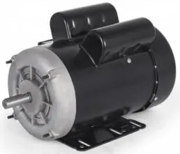
Refer to the technical data tables in the manual for specific model details, including Horsepower (HP), Frame Size, Rated Current, RPM, and Voltage (115V/230V). Motors are TEFC (Totally Enclosed Fan Cooled) with Class F insulation and IP23 protection.
Connection Methods
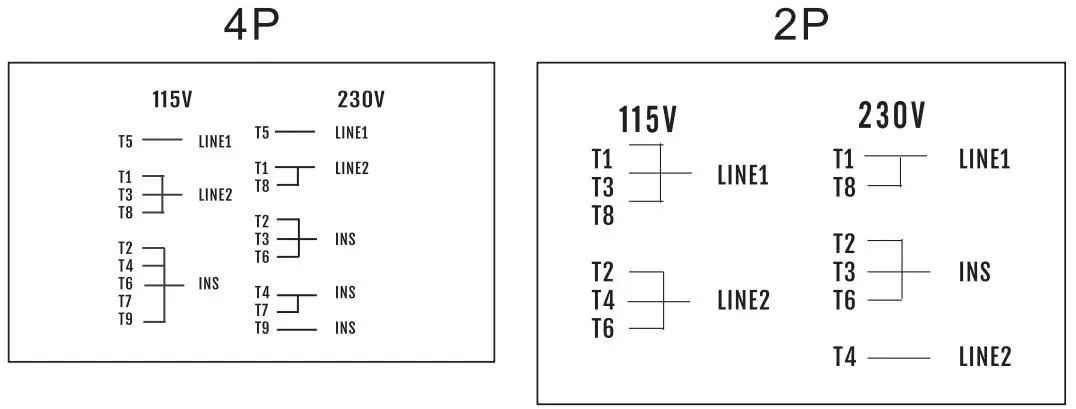
The manual provides specific wiring diagrams for 2P and 4P motors. Factory settings are typically for 115V/60Hz. Ensure wiring matches the provided diagrams for your specific voltage (115V or 230V). Changing rotation from CCW to CW involves swapping T6 and T8 leads.
Troubleshooting
If the motor fails to start or operates abnormally, check the power supply voltage and wiring connections. If the motor overheats and stops, it may be due to overload; allow it to cool for at least 30 minutes, then press the red protector button to reset.
Manufacturer information
VEVOR
Practical help
Common problems
Motor shaft cannot be rotated manually upon receipt
The concentricity may have been damaged during transport. Use a wooden or rubber hammer to gently tap the shaft, front end cover, and back end cover to adjust concentricity until the shaft turns flexibly.
Motor does not work when powered on
Check the power supply voltage, verify wiring against the diagram, and press the red protector button to reset.
Motor rotates slowly and cannot start normally
Check power supply voltage, verify wiring, and inspect the motor capacitor for good condition.
Motor overheats and stops working
This indicates an overload. Allow the motor to cool for 30 minutes, then press the red protector button to reset.
Before use
- Verify that the power supply voltage and frequency match the motor nameplate.
- Ensure the motor has a proper grounding connection.
- Check that the shaft rotates freely by hand.
- Inspect the electrical outlet box and contacts for cleanliness.
- Confirm the motor is securely fastened.
Specs in practice
- Horsepower (HP)
- The power rating of the motor, ranging from 3/4HP to 2HP depending on the model.
- Rated Current
- The electrical current draw at rated load, specified for 115V/230V.
- Rated Speed (RPM)
- The rotational speed of the motor shaft under load (e.g., 1725 or 3450 RPM).
Images and diagrams
- Wiring diagrams are provided for both 2P and 4P motor configurations.
- Diagrams show connections for 115V and 230V power supplies.
- T1-T9 represent the motor lead wire numbers.
- INS indicates a parallel connection.
Model compatibility
- Motors are designed for single-phase operation.
- Suitable for use in various environments but requires protection from dust and foreign bodies.

Manual page author
Michael Turner
Technical manual editor
Reviews PDF manuals for structure, safety notes, and practical product details so readers can find the right information quickly.