Industrial / Pumps & Motors
User Guide for Vickers by Danfoss PVM Variable Displacement Piston Pump
Comprehensive user guide for the Vickers by Danfoss PVM series variable displacement piston pumps. Includes installation, start-up procedures, control options, performance specifications, and model code selection.
Table of contents
Manual images
Click an image to enlargeQuick guide from the manual
This guide provides essential information for the installation and operation of the Vickers by Danfoss PVM series variable displacement piston pumps. Before starting, ensure the reservoir and circuit are clean and free of debris. The pump case must be filled with hydraulic fluid through the uppermost drain port before initial start-up. Verify the direction of rotation matches the model designation and ensure the case drain line is connected directly to the reservoir, terminating below the oil level.
Introduction
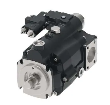
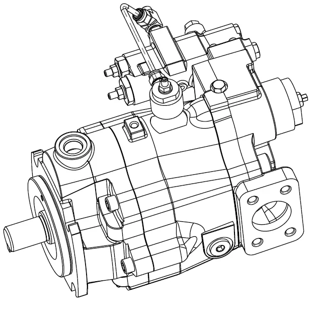
The PVM series pumps are open circuit, axial piston designs featuring a saddle-type yoke with steel-backed polymer bearings. They are designed for high-pressure industrial applications, offering quiet operation and high efficiency. Typical applications include mining machinery, injection molding, metal forming, and oil and gas equipment.
Model Code Selection
The model code defines the pump configuration. Key parameters include:
- Displacement: 098 (98.3 cm³/r) or 106 (106.5 cm³/r).
- Valve Plate: Industrial (E) or High speed (M).
- Input Rotation: Clockwise (R) or Counter-clockwise (L).
- Control Options: Pressure Compensator (A), Load Sensing (B/C), or Industrial Control (E/F).
- Mounting Flange: SAE J744-127-4 C 4-Bolt.
Control Options
The PVM series offers various control configurations to match system demands:
- Pressure Compensator (Code A): Provides modulated flow to meet load demands at a pre-adjusted pressure.
- Load Sensing (Code B/C): Matches pump output to system load demand, maximizing efficiency.
- Industrial Control (Code E/F): Intended for remote or electronically controlled settings.
- Power Control (Code L): Limits maximum torque output by reducing displacement as pressure increases.
Installation and Start-up
Proper installation is critical for pump longevity:
- Mounting: Can be horizontal or vertical. Ensure the case remains full of fluid.
- Drive: Direct coaxial drive through a flexible coupling is recommended.
- Start-up Procedure:
- Clean the system by flushing and filtering.
- Fill the reservoir with filtered oil.
- Fill the pump case through the uppermost drain port.
- Start the pump and allow it to prime (should take a few seconds).
- Operate unloaded for 5-10 minutes to remove trapped air.
Performance and Specifications
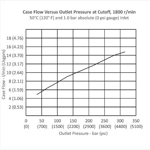
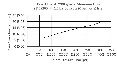
The manual provides detailed performance charts for different speeds (1000-2200 rpm) and pressures (up to 315 bar). Always refer to the specific performance curves for your model (PVM098 or PVM106) regarding noise levels, efficiency, and input power requirements.
Fluid Requirements
Use anti-wear hydraulic oil or automotive type crankcase oil (SC, SD, SE, or SF per SAE J183 FEB80). Maintain a contamination level of 20/18/13 (Danfoss) or ISO 18/13. High-water-content and phosphate ester fluids are also supported.
Manufacturer information
Danfoss A/S
Practical help
Common problems
Pump does not prime
Check for restrictions between the reservoir and the inlet, ensure the pump is rotating in the correct direction, and check for air leaks in the inlet line.
Excessive noise
Ensure the reservoir is filled to a level sufficient to prevent vortexing at the suction connection.
Before use
- Ensure reservoir and circuit are clean and free of dirt/debris.
- Fill reservoir with filtered oil to prevent vortexing at suction.
- Fill pump case through the uppermost drain port with hydraulic fluid.
- Verify correct direction of shaft rotation.
- Ensure case drain line is connected directly to the reservoir and terminates below the oil level.
Specs in practice
- Nominal Pressure
- Maximum continuous operating pressure.
- Peak Pressure
- Maximum allowable pressure for short durations (less than 0.5 seconds).
- Displacement
- Volume of fluid moved per revolution (cm³/r).
Images and diagrams
- Model Code Selection: Explains how to decode the pump configuration (displacement, control type, shaft, etc.).
- Control Schematics: Diagrams for Pressure Compensator, Load Sensing, and Power Control configurations.
Model compatibility
- Compatible with petroleum-based, synthetic, high-water-content, and phosphate ester fluids.
- Requires ISO 18/13 or better fluid cleanliness.

Manual page author
Emily Carter
User documentation editor
Prepares concise manual descriptions and highlights the most useful setup, operation, and maintenance information for readers.