Electronics / Marine Navigation
Installation Guide for Garmin 1.2L and 2.0L Hydraulic Pump
Installation and setup guide for the Garmin 1.2L and 2.0L hydraulic pump. Includes mounting instructions, hydraulic layout diagrams, hose connection steps, and maintenance tips.
Table of contents
Quick guide from the manual
This document provides installation instructions for the Garmin 1.2L and 2.0L hydraulic pumps. Before beginning, ensure your vessel's steering system has a vented reservoir; installing this pump on a system with an unvented reservoir will cause damage. The pump must be installed in a dry location, protected from water and weather. Always bleed all air from the hydraulic system before attempting to use the autopilot.
Tools Needed
- Safety glasses, drill, and drill bits
- Wrenches, wire cutter/stripper
- Screwdrivers (Phillips and flat)
- Cable ties and marine corrosion inhibitor spray
- Mounting screws (if included screws are not suitable for the surface, provide appropriate ones)
- Hydraulic hardware: -4 (6 mm / 1/4 in.) ID or larger hose (1000 psi rating), T-connectors, shutoff valves, liquid thread sealant (e.g., LOCTITE 567), hydraulic bleeding equipment, and hydraulic fluid
Mounting Considerations
Proper mounting is critical for system performance:
- The pump must be located within 19 in. (0.5 m) of the ECU.
- Pump cables cannot be extended.
- Install the pump near the cylinder so that no more than 3 m (10 ft.) of hydraulic hose connects the pump to the cylinder.
- Mount the pump horizontally if possible. If vertical mounting is necessary, the pump head connectors must face up.
Mounting the Pump
- Hold the pump in the intended location and mark the mounting holes using the pump as a template.
- Drill the four holes through the mounting surface using an appropriate drill bit.
- Secure the pump to the mounting surface using the selected hardware.
Hydraulic Considerations
Important: Do not use thread seal tape (such as Teflon tape) or thread putty on any hydraulic fitting. Small debris can enter the system and render the autopilot or steering inoperable. This voids the warranty. Use liquid thread sealant only on fittings without O-rings.
Connecting the Hydraulic Hoses
- Disconnect necessary hoses from the hydraulic system.
- Add a T-connector to the starboard and port hoses between the helm and the steering cylinder.
- If the boat lacks a return hose, add one to connect the helm to the pump. If a return hose exists, add a T-connector to it.
- Connect the port and starboard hoses from the T-connectors to the appropriate pump fittings.
- Install the Shadow Drive valve in the port or starboard hydraulic hose between the helm and the T-connector.
Completing the Installation
- Install remaining autopilot components as per the autopilot corepack instructions.
- Bleed the air from the hydraulic system.
- Apply marine corrosion inhibitor spray to the pump body and manifold. Re-apply annually.
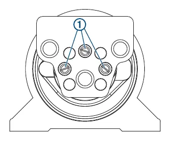
Engaging and Disengaging the Shutoff Valves
The pump features three shutoff valves to isolate it for troubleshooting or repair. When engaged, the boat steers normally, but the autopilot cannot control the steering system. To engage, fully tighten the valve screws. To disengage, fully loosen the valve screws. Do not force the screws past the stopping point.
Configuration and Service
If the boat tends to steer gradually to one side while in standby due to uneven rudder loads, you can install an autopilot check valve kit (010-11203-10) to block the bleed down path.
Manufacturer information
Garmin Ltd.
Practical help
Common problems
Gradual turn in one direction while in standby
Install an autopilot check valve kit (010-11203-10) to block the bleed down path.
Pump damage
Ensure the steering system has a vented reservoir. Unvented reservoirs will damage the pump.
System inoperable due to debris
Do not use thread seal tape or thread putty on hydraulic fittings. Use liquid thread sealant only where required.
Before use
- Verify the steering system has a vented reservoir.
- Ensure the pump is installed in a dry location.
- Check that hydraulic hoses are -4 (6 mm / 1/4 in.) ID or larger.
- Confirm the pump is mounted horizontally or vertically with connectors facing up.
- Bleed all air from the hydraulic system.
Specs in practice
- Temperature range
- -10° to 60°C (14° to 140°F)
Images and diagrams
- Single Helm without Power Assist: Shows connection points for Shadow Drive valve, pump, helm, and steering cylinder.
- Dual-Helm without Power Assist: Shows routing for two helm stations.
- Single Helm with Power Assist: Shows pump placement between cylinder and power-assist module.
Model compatibility
- Only for use with Garmin autopilot systems.
- Cannot be installed on a system with an unbalanced cylinder.

Manual page author
Michael Turner
Technical manual editor
Reviews PDF manuals for structure, safety notes, and practical product details so readers can find the right information quickly.