Plumbing / Showers & Tubs
Installation and User Manual for Hansgrohe Croma C 100 3-Jet Shower Head
Quick guide for the Hansgrohe Croma C 100 3-Jet shower head. Includes installation steps, spray mode adjustment, cleaning instructions, and warranty information.
Table of contents
Manual images
Click an image to enlargeQuick guide from the manual
This document provides installation and maintenance instructions for the Hansgrohe Croma C 100 3-Jet shower head. For optimal performance, Hansgrohe recommends installation by a licensed professional plumber. Ensure you have all necessary tools before beginning. The shower head is designed for use with automatic compensating valves rated at 1.9 GPM (7.2 L/min) or less.
Installation Considerations
- Temperature Safety: To prevent scald injury, the maximum output temperature of the shower mixing valve must not exceed 120°F (49°C). In Massachusetts, the limit is 112°F (44°C).
- Compatibility: This unit must be used with automatic compensating valves rated at 1.9 GPM (7.2 L/min) or less.
- Professional Installation: Hansgrohe recommends that this unit be installed by a licensed, professional plumber.
Tools Required
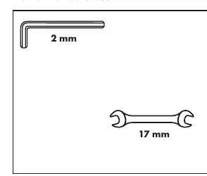
- 2 mm hex key
- 17 mm wrench
Installation Steps
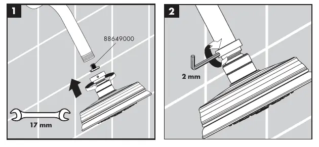
- Ensure the water supply is off.
- Attach the shower head to the shower arm using the 17 mm wrench.
- Secure the connection using the 2 mm hex key as shown in the installation diagram.
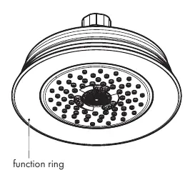
Operation
To change the spray modes, simply turn the function ring located on the shower head to the desired spray mode.
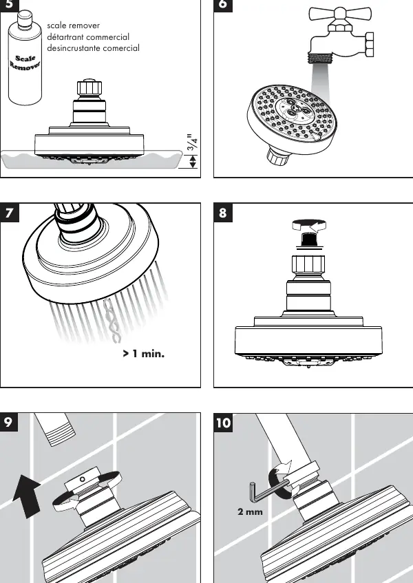
Cleaning and Maintenance
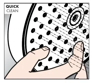
The shower head features the QuickClean system. To remove lime scale, simply rub over the flexible silicone spray nozzles with your fingers. For deeper cleaning, you may use a scale remover, but follow these guidelines:
- Do not use: Cleaners containing hydrochloric acid, formic acid, lye, or acetic acid; abrasive powders, pads, or brushes; steam cleaners; or "no-rinse" cleaning agents.
- Application: Do not spray cleaners directly onto the product. Spray the cleaner onto a soft cloth or sponge first.
- Rinsing: Always rinse the product thoroughly with clear water after cleaning and polish dry with a soft cloth.
Warranty Information
Hansgrohe, Inc. offers a limited warranty on its products. The warranty covers defects in material and workmanship for the original consumer purchaser. It does not cover damage resulting from misuse, improper installation, outdoor use, freezing water, excessive water pressure, or the use of improper cleaning agents. For warranty service, contact Hansgrohe, Inc. at 1492 Bluegrass Lakes Parkway, Alpharetta, GA 30004, or call 800-334-0455.
Manufacturer information
Hansgrohe SE
Practical help
Common problems
Lime scale buildup on nozzles
Rub the flexible silicone nozzles with your fingers to break up and remove the scale.
Damage to finish or material
Avoid using abrasive cleaners, steam cleaners, or chemicals containing hydrochloric, formic, or acetic acid. Always spray cleaner on a cloth first, not directly on the product.
Before use
- Verify you have a 2 mm hex key and a 17 mm wrench.
- Ensure the shower mixing valve is set to a maximum output of 120°F (49°C).
- Confirm the system uses an automatic compensating valve rated at 1.9 GPM or less.
- Inspect the product for any visible damage before installation.
- Keep your receipt as proof of purchase for warranty claims.
Specs in practice
- Max Temperature
- 120°F (49°C) generally; 112°F (44°C) in Massachusetts.
Images and diagrams
- The installation diagram illustrates using a 17 mm wrench to tighten the shower head and a 2 mm hex key to secure the locking mechanism.
- The function ring diagram shows the rotating part on the shower head used to switch between spray modes.
Model compatibility
- Must be used with automatic compensating valves rated at 1.9 GPM (7.2 L/min) or less.

Manual page author
Emily Carter
User documentation editor
Prepares concise manual descriptions and highlights the most useful setup, operation, and maintenance information for readers.