Power / Energy Storage Systems
Installation Guide for Hoymiles HBX-10LV-USG1 Low Voltage Battery
Quick installation guide for the Hoymiles HBX-10LV-USG1 low voltage battery. Includes wall mounting steps, electrical connection diagrams, system configuration, and LED status indicators.
Table of contents
Manual images
Click an image to enlargeQuick Installation Guide
This guide provides essential instructions for the installation and setup of the Hoymiles HBX-10LV-USG1 low voltage battery. Before beginning, ensure all installers are qualified, trained in grid-connected photovoltaic systems, and equipped with insulated tools and personal protective equipment. Verify that the battery pack is turned off and all circuit breakers are disconnected before starting the installation.
Packing List
Ensure all components are present before installation:
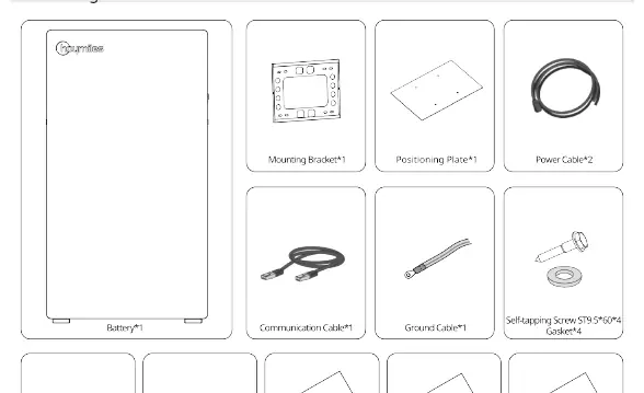
- Battery unit
- Mounting bracket
- Positioning plate
- Power cables (x2)
- Communication cable
- Ground cable
- Self-tapping screws (ST9.5*60) and gaskets
- M5*16 screws
- RJ45 waterproof terminals
- Packing list, inspection report, and installation guide
Product Overview
The battery unit features the following key components:
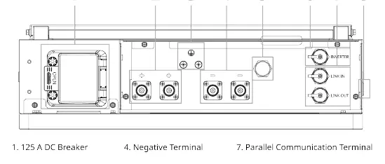
- 125 A DC Breaker: Main power disconnect.
- Terminals: Positive and Negative terminals for power connection.
- GND: Grounding point.
- Communication Ports: Inverter, Link In, and Link Out terminals.
- Breather Valve: Pressure equalization.
- Power Switch: Used to activate the battery.
Wall Mounting Steps
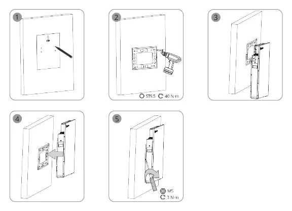
Follow these steps to mount the battery securely:
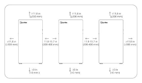
- Ensure minimum clearances: 300mm on sides and top, 0mm at the bottom.
- Use the positioning plate to mark drilling locations.
- Drill holes and secure the mounting bracket using the provided ST9.5 screws (torque: 40 N·m).
- Hang the battery unit onto the mounting bracket.
- Secure the battery to the bracket using M5 screws (torque: 3 N·m).
Electrical Connection
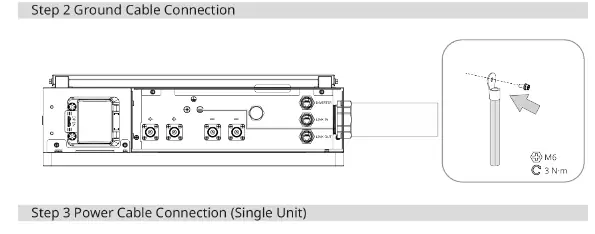
Grounding: Connect the ground cable to the GND terminal using an M6 screw (torque: 3 N·m).
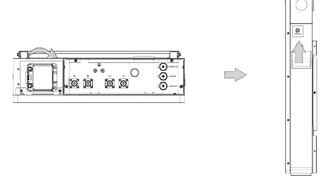
Power Cables: Connect the positive and negative cables to the respective terminals. Ensure cables are 1 AWG / 50 mm².
Communication Cables: Connect the communication cable between the inverter and the battery, or between batteries in a parallel configuration using the Link In/Link Out ports.
System Activation
- Open the circuit breaker cover and turn on the circuit breaker.
- Turn on the power switch.
- Wait five seconds; a blue indicator light should flash, confirming normal operation.
- Replace the top covers and tighten the screws.
Indicator Status
The LED indicator provides system status:
- Standby: On 0.25s; Off 3.75s.
- Charge: On 0.5s; Off 1.5s.
- Discharge: Stays lit.
- Protection Status: On 0.5s; Off 0.5s.
- Inverter Communication Fault: On 0.5s; Off 0.5s.
- Parallel Communication Fault: On 0.25s; Off 3.75s.
- Alarm/Fault: Stays lit.
- Shutdown: Off.
Practical help
Common problems
Inverter Communication Fault
Check the communication cable connection between the battery and the inverter.
Parallel Communication Fault
Verify the link cables between parallel battery units are securely connected.
Indicator light is off
Ensure the circuit breaker is turned on and the power switch is activated.
Before use
- Ensure battery is turned off and circuit breakers are disconnected.
- Verify all components from the packing list are present.
- Ensure installers are qualified and trained in PV systems.
- Prepare insulated tools and personal protective equipment.
- Check wall mounting surface for required clearances (300mm sides/top).
Specs in practice
- Ground Cable
- 10 AWG / 6 mm²
- Mounting Torque (ST9.5)
- 40 N·m
- Mounting Torque (M5/M6)
- 3 N·m
Images and diagrams
- Single Unit: Direct connection to inverter.
- Parallel Connection: Requires busbar or direct link depending on configuration.
Model compatibility
- For parallel connection without busbar, charge/discharge power must not exceed 12 kW.

Manual page author
David Miller
Documentation analyst
Organizes user manual content into clear summaries, with attention to model details, product context, and everyday usability.