Power / Energy Storage Systems
Quick Reference Guide for Savant Power Storage 20 [100A]
Quick reference guide for the Savant Power Storage 20 [100A]. Includes installation steps, wiring diagrams, status LED meanings, and technical specifications.
Table of contents
Manual images
Click an image to enlargeQuick Guide
This document provides a quick reference for the Savant Power Storage 20 [100A] system. It covers installation, wiring, and status indicators. For detailed deployment and configuration, refer to the Savant Power Storage 20 Deployment Guide and App Setup Guide.
Specifications
Environmental:
- Inverter Temperature: -13°F to 131°F (-25°C to 55°C)
- Battery Temperature: 32°F to 113°F (0°C to 45°C)
- Humidity: 0% to 95% Relative Humidity (non-condensing)
- Altitude: Less than 9842 ft
- Rating: NEMA4X
Power & Capacity:
- Battery Capacity: 52 Ah / 20 kWh
- Maximum Power: 12.5 kW
- Maximum Output Current: 100A
- Grid Transfer Time: < 70ms
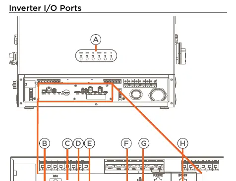
Inverter Panel & Ports
The inverter features several key interfaces:
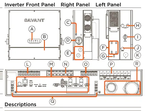
- ON/OFF Button: Powers the system on or off.
- Grid Switch: Connects or disconnects the Grid input.
- Network: RJ-45 LAN connection.
- PV Inputs: MPPT Inputs.
- I/O Ports: Includes USB ports for software updates, SD slot for data collection, and BCMS port for battery communication.
Status LEDs
Network LEDs:
- Solid Red: Startup in progress.
- Blinking Green: Connecting to router.
- Solid Green: Internet connected.
Status LEDs:
- Solid Green: Running normally.
- Blinking Red: Communication fault.
- Solid Red: Internal communication fault.
Power LEDs:
- On: Grid, Generator, or Load power operating normally.
- Off: No power input.
Battery Status Panel
The battery system includes a status panel with the following indicators:
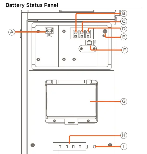
- Power Switch: Toggles ON or OFF all batteries.
- Reset Button: Restarts the battery system.
- Start Button: Starts the battery system.
- Status LED: Indicates system health (Solid Green for normal, Solid Red for protection/fault).
Installation
Bracket Installation:
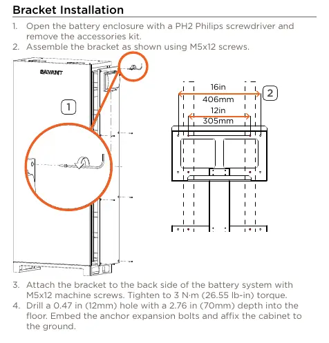
- Open the battery enclosure and remove the accessories kit.
- Assemble the bracket using M5x12 screws.
- Attach the bracket to the back of the battery system (Torque: 3 N·m).
- Drill holes in the floor, embed anchor bolts, and affix the cabinet.
- Install the bracket on the wall using M6x50 tapping screws.
Inverter Installation:
- Remove the battery seal cap (BAT/COM) and communication cable panel.
- Hang the inverter on the bracket.
- Fasten the inverter to the bracket with M5x12 screws (Torque: 3 N·m).
- Connect the inverter and battery cabinet with the conduit and screw kit.
- Plug in battery modules from the bottom up and fasten with M4x8 screws (Torque: 1.2 N·m).
Wiring
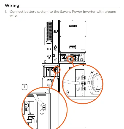
- Connect the battery system to the inverter with a ground wire.
- Make REF, BAT-, and BAT+ connections from the inverter to the battery access panel through the conduit.
- Connect the DC 12V wire between the inverter and the battery access panel.
- Connect the BCMS port of the inverter to the CANBUS connection on the Battery Status Panel.
- Complete connections for Grid, Load, and Generator.
- Connect the system to the network switch using a CAT5 or higher Ethernet cable.
Practical help
Common problems
Inverter Status LED Solid Red
Indicates an energy management unit internal communication fault.
Inverter Status LED Blinking Red
Indicates a communication fault between the energy management unit and the battery, inverter, or PV unit.
Battery Status LED Solid Red
A protection or fault has been detected in the battery system.
Power LED Off
No power input detected.
Before use
- Ensure the mounting surface can support the weight (600 lbs / 272.15 kg).
- Verify all battery modules are labeled 1-8 before installation.
- Ensure the battery enclosure is opened with a PH2 Philips screwdriver.
- Check that all conduit connections are secure.
- Confirm the network switch is ready for connection.
Specs in practice
- Inverter Temperature
- Operating range: -13°F to 131°F (-25°C to 55°C).
- Battery Capacity
- 52 Ah / 20 kWh total capacity.
- Maximum Output Current
- 100A maximum passthrough per inverter.
- Grid Transfer Time
- Less than 70ms.
Images and diagrams
- Inverter Front Panel: Shows status LEDs, ON/OFF button, grid switch, and conduit knockouts.
- Battery Access Panel: Shows power switch, reset button, start button, and status LEDs.
- Wiring Diagram: Illustrates connections for Grid, Load, Generator, PV array, and Network.
Model compatibility
- Requires Savant Power Storage 20 Deployment Guide for full configuration.
- Wi-Fi: 2.4 GHz IEEE 802.11 b/g/n.

Manual page author
Michael Turner
Technical manual editor
Reviews PDF manuals for structure, safety notes, and practical product details so readers can find the right information quickly.