Power / Solar Inverters
User Manual for Huawei MERC-(1300W, 1100W)-P Smart PV Optimizer
Quick guide for the Huawei MERC-(1300W, 1100W)-P Smart PV Optimizer. Includes installation instructions, cable connection procedures, commissioning via FusionSolar app, and troubleshooting steps.
Table of contents
Manual images
Click an image to enlargeQuick guide from the manual
The Huawei Smart PV Optimizer is a DC-DC converter installed on the rear of PV modules. It manages the maximum power point (MPP) of each module to improve energy yield and provides module-level shutdown and management. This guide covers installation, cable connection, commissioning, and troubleshooting.
Product Overview
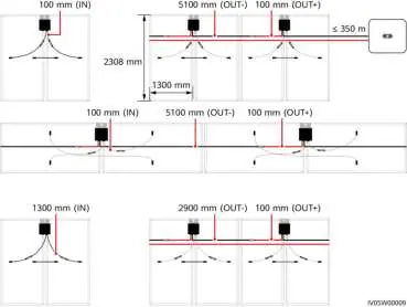
The optimizer is delivered with two types of input power cables: long (1300 mm) or short (100 mm). Select the optimizer based on the PV module cable length:
- For PV modules with long cables, select optimizers with short input cables.
- For PV modules with short cables, select optimizers with long input cables.
Installation Requirements
Ensure the following conditions are met before installation:
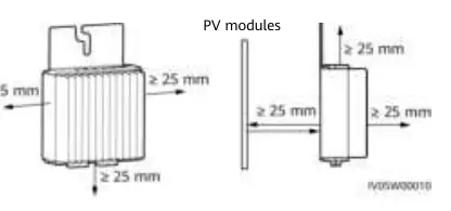
- Clearance: Maintain at least 25 mm of clearance around the optimizer for ventilation.
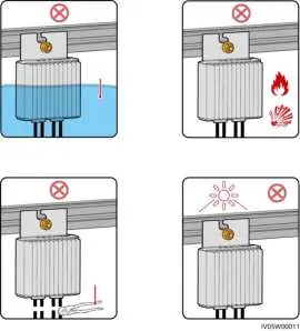
- Environment: Do not install in positions that may be submerged in water. Avoid direct sunlight.
- Temperature: Recommended ambient temperature is 70°C or less. If it exceeds this, the optimizer may shut down for overtemperature protection and recover automatically once cooled.
- Safety: Do not store flammable or explosive materials in the installation area. Do not cut the delivered cables.
Installing the Optimizer
Select the installation mode based on your mounting scenario:

- Extruded Aluminum Profile: Use a T-shaped bolt and nut (purchased separately).
- PV Module Frame (Bolt Assembly): Ensure a mounting hole is reserved on the frame. Use bolt assembly and nut (purchased from a third party).
- PV Module Frame (Frame Mounting Bracket): Purchase the bracket separately. Install the optimizer before the PV module.
After determining the position, remove the SN label from the optimizer and attach it to the physical layout template.
Installing Optimizer Cables
Ensure input (IN) and output (OUT) cables are correctly connected to avoid device damage. The typical output voltage (V1) of a single optimizer is 1 V.
- Connect the optimizer input (IN) cable to the PV module connection box.
- Connect the output (OUT) cables to the adjacent optimizer or solar inverter.
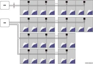
- Route AC and DC power cables in different troughs or pipes with at least 10 cm spacing.
- Route the home-run cable next to the cables between PV modules to reduce EMC impact.
Power-On Commissioning
Use the FusionSolar app for commissioning:
- Open the FusionSolar app and log in to the installer account.
- Choose Me > Device commissioning and connect to the solar inverter's WLAN hotspot.
- Select installer, enter the password, and log in.
- Choose Device monitoring, select the PV string, and check the optimizer status.
Troubleshooting
Check the optimizer status in the FusionSolar app:
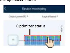
- Green: Running properly.
- Gray: Offline. Check SN and location information, then search again.
- Red: Faulty.
- Yellow: Disconnected.
If changes occur (adding/deleting/replacing optimizers), turn off DC and AC switches, wait 5 minutes, perform the operation, and run the optimizer search again.
Replacing an Optimizer
- Power off the solar inverter and remove the faulty optimizer.
- Install the new optimizer and connect cables.
- Power on the inverter, log in to the app, choose Devices > Inverter, and tap Optimizer Search.
- Choose Devices > Connected devices > Optimizer, select the faulty optimizer, and tap Device Replacement.
Precautions
- Use Staubli MC4 DC connectors.
- Optimizers are not supported in off-grid scenarios.
- Partial configuration is not allowed; all PV modules must be connected to optimizers.
- Use insulated tools and proper PPE during installation.
Manufacturer information
Huawei Technologies Co., Ltd.
Practical help
Common problems
Optimizer offline (Gray status)
Check if SN and location information are correct, then search for the device again.
Optimizer faulty (Red status)
Contact your installer.
Voltage V1 < 0.95V
Check if irradiance is adequate, ensure input cables are connected, check cable connections, or replace the optimizer.
Overtemperature protection
Check ventilation and ambient temperature at the installation position. Improve ventilation if necessary.
PV string voltage is 0
Check if the PV string is open-circuited or if cables are connected to the wrong string.
Before use
- Ensure ambient temperature is <= 70°C.
- Verify PV module cable length to select the correct optimizer cable type (long vs short).
- Ensure installation area is not submerged in water.
- Have insulated tools and proper PPE ready.
- Ensure Staubli MC4 connectors are used.
- Plan installation to keep communication distance within 350m.
Specs in practice
- Max communication distance
- 350m between the optimizer and the solar inverter.
- Input cables
- Available in 1300mm or 100mm lengths.
Images and diagrams
- Wiring diagrams illustrate correct routing for single and multi-string installations to minimize EMC impact.
- Mounting diagrams show T-shaped bolt, bolt assembly, and frame bracket installation methods.
Model compatibility
- Not supported in off-grid scenarios.
- Partial configuration is not allowed; all PV modules must be connected to optimizers.
- Requires Staubli MC4 DC connectors.

Manual page author
David Miller
Documentation analyst
Organizes user manual content into clear summaries, with attention to model details, product context, and everyday usability.