Power / Solar Inverters
User Manual for Huawei SUN2000-100KTL-M2, 110KTL-M2, 115KTL-M2 Solar Inverter
Quick guide for installing and commissioning the Huawei SUN2000-100KTL-M2, 110KTL-M2, and 115KTL-M2 solar inverters. Includes cable connection diagrams, mounting instructions, and app setup.
Table of contents
Manual images
Click an image to enlargeQuick guide from the manual
This document provides essential instructions for the installation, electrical connection, and commissioning of the Huawei SUN2000-(100KTL, 110KTL, 115KTL)-M2 solar inverters. It is intended for certified electricians. Always use insulated tools and appropriate personal protective equipment (PPE) during installation.
Overview
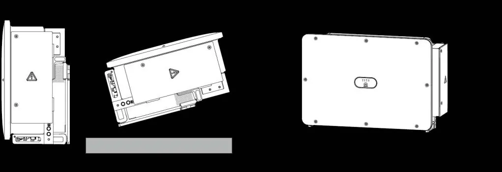
The inverter features a main panel, LED indicators, a maintenance compartment door, a mounting bracket, and an external fan tray. The bottom of the unit contains DC input terminals (PV1–PV20), DC switches, reset buttons, a USB port, a communications port (COM), and cable entries for AC and tracking system power.

Installation Requirements
Ensure the installation site is suitable. If installed in areas with abundant vegetation, harden the ground underneath using cement or gravel (recommended area: 3 m x 2.5 m). Maintain a clearance of at least 600–730 mm underneath the inverter for ventilation and maintenance.
Installing a Solar Inverter
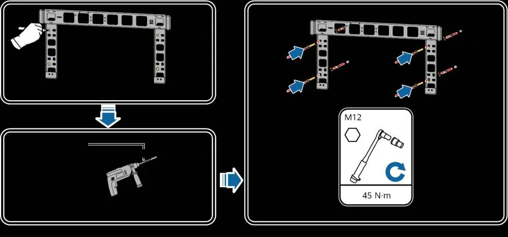
The inverter is mounted on a support structure. Use the provided M12x40 bolt assemblies. Before installing the mounting bracket, remove the security Torx wrench. Use the optional handles for transportation and installation, ensuring they are securely attached and removed after the process is complete.
Connecting Cables
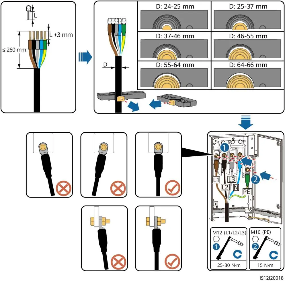
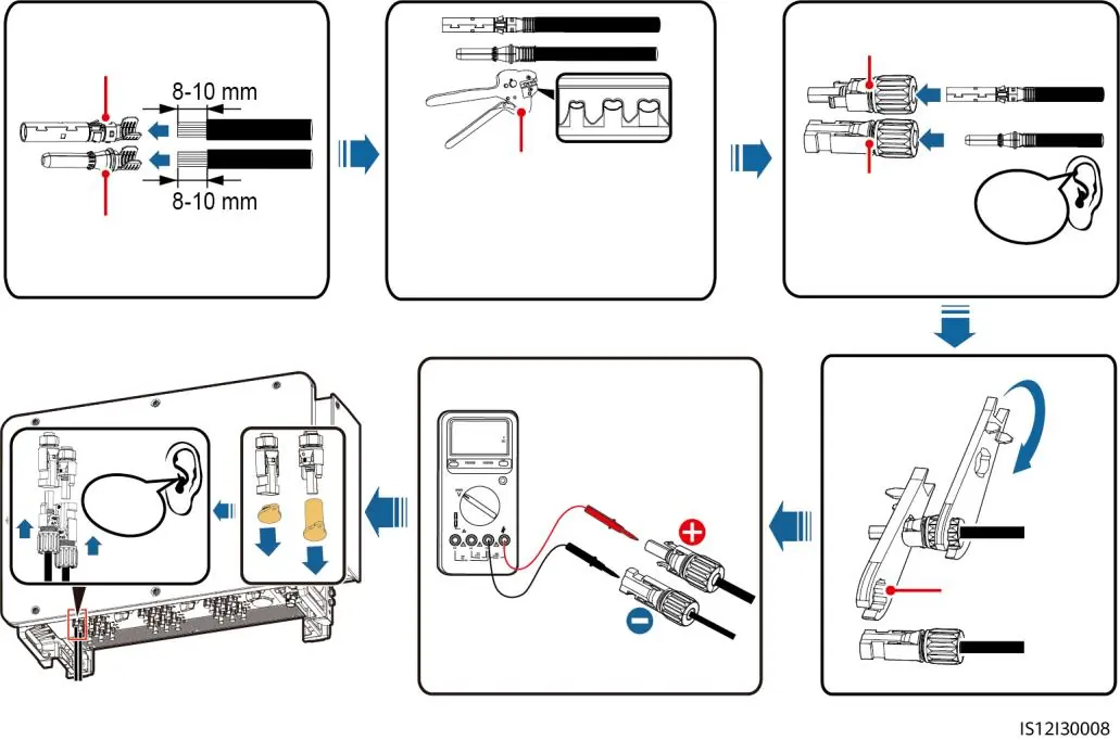
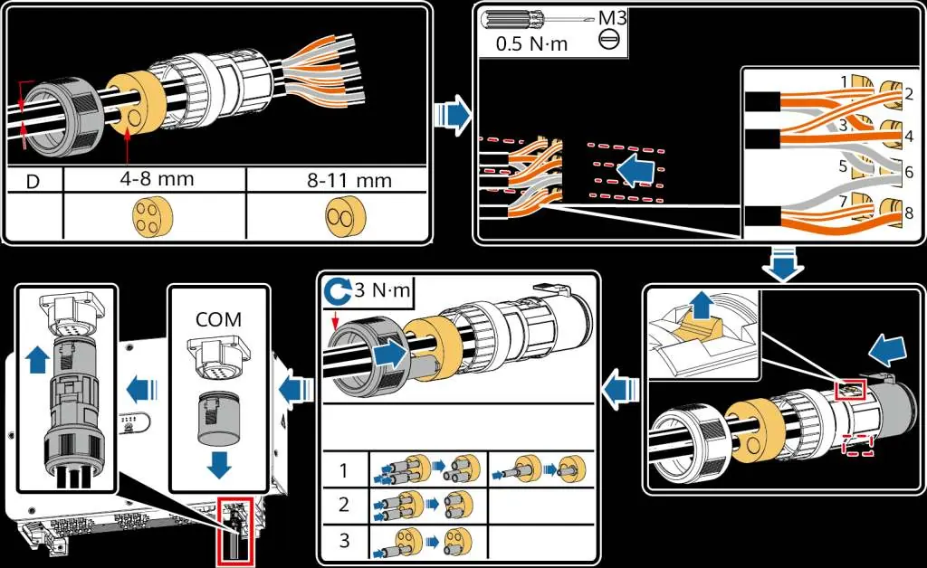
Follow local laws and regulations for cable connections. Ensure sufficient slack is provided to prevent overstress. The inverter supports various cable types, including multi-core and single-core AC output cables. Use the crimping module and rubber rings appropriate for the cable diameter. Ensure the PE cable is connected to a nearby ground point. For DC inputs, evenly distribute cables across the three DC switches, with DC SWITCH 1 preferred. Always measure DC voltage with a multimeter before connection; if voltage is negative, correct the polarity. If voltage exceeds 1100V, reduce the number of PV modules.
Powering On the System
Before powering on, verify the installation: ensure the inverter is secure, switches are OFF, cables are connected correctly, and unused ports are sealed. Turn on the AC switch between the inverter and the grid, then set DC SWITCH 1 to ON. Once the PV connection indicator is steady green, set DC SWITCH 2 and 3 to ON. Monitor the LED indicators to confirm the operating status.
Commissioning
Use the FusionSolar app (for FusionSolar management systems) or the SUN2000 app (for other systems) to configure the inverter. Connect via WLAN, Bluetooth, or USB. Upon first login, set a secure password. Ensure the correct grid code is selected based on the application area.
Manufacturer information
Huawei Technologies Co., Ltd.
Practical help
Common problems
DC switches turn off automatically
This indicates a fault. Contact technical support; do not attempt to turn the switches on manually.
Negative DC voltage measured
The DC input polarity is incorrect. Correct the polarity before proceeding.
DC voltage exceeds 1100V
Too many PV modules are configured to the same string. Remove some PV modules.
Inverter not grid-tied
Check the grid connection indicator. If off, the inverter is not grid-tied. Ensure AC switch is ON.
Before use
- Ensure all cables are connected correctly and securely.
- Verify that the installation space is proper and the environment is clean.
- Check that DC switches and the downstream AC switch are set to OFF.
- Ensure unused DC input terminals are sealed.
- Verify that unused USB ports are plugged with watertight caps.
- Ensure the maintenance compartment door is closed and screws are secured.
Specs in practice
- Max DC Input Voltage
- 1100V. Do not exceed this limit.
- AC Cable Type
- Supports multi-core and single-core cables; cross-sectional area depends on material (Copper/Aluminum).
Images and diagrams
- Port layout diagram identifies DC inputs, switches, and communication ports.
- Cable connection diagrams illustrate the correct method for multi-core and single-core AC cables.
- DC input selection table guides the distribution of PV inputs across switches.
Model compatibility
- Supports RS485 and MBUS communication.
- FusionSolar app recommended for FusionSolar smart PV management system.
- SUN2000 app recommended for other management systems.

Manual page author
David Miller
Documentation analyst
Organizes user manual content into clear summaries, with attention to model details, product context, and everyday usability.