Industrial / Energy Monitoring
Installation Guide for Janitza JPC 100-WEB Smart Energy Panel
Quick installation and configuration guide for the Janitza JPC 100-WEB Smart Energy Panel. Includes mounting instructions, connection diagrams, network settings, and device configuration procedures.
Table of contents
Manual images
Click an image to enlargeQuick Guide
The JPC 100-WEB is a Smart Energy Panel designed for installation in control cabinets. This guide covers the essential steps for mounting, connecting, and configuring the device. Ensure you have read the full safety instructions before proceeding.
Safety Information
DANGER: Electrical voltage can cause severe injury or death. Always switch off the installation before commencing work and verify it is de-energized.
- Only qualified personnel with electrical training should work on the device.
- Observe national accident prevention regulations and safety standards.
- Do not exceed the limit values specified in the user manual and on the rating plate.
- The device is not intended for installation in vehicles or environments with harmful oils, acids, gases, or vapors.
Installation
The device is designed for panel mounting.
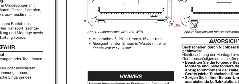
- Prepare an installation cutout of 261 ±1 mm x 164 ±1 mm.
- Ensure the wall thickness is a maximum of 3 mm.
- Insert the device into the cutout from the front.
- Insert the retaining brackets into the provided openings.
- Push the brackets towards the back until flush.
- Insert the fastening screws and tighten them. Important: Tighten in the sequence: upper, middle, then lower brackets. The maximum tightening torque is 0.25 to 0.3 Nm.
Connection
The JPC 100-WEB connects to gateway/master devices via Ethernet. It can also act as a master in a bus system via the RS-485 interface.
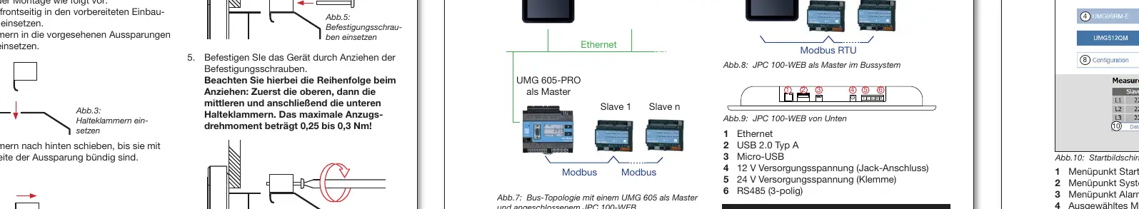
- Ethernet: Connects to master devices.
- RS-485: 3-wire connection (C/GND, B, A).
- Power Supply: 24 V DC (terminal) or 12 V DC (jack).
User Interface and Login
Access the user interface to change system settings and configure connected measurement devices.
- Default Login: User: admin, Password: 1234.
- Roles: Read access, Operator, Administrator.
- Change the admin password via: System > User Settings > User Management > Admin Password.
System Settings
Configure network and communication settings via the System menu.
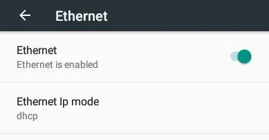
- TCP/IP: Supports DHCP (factory default) and static IP addresses. Change via Hardware settings > Ethernet.
- Modbus/TCP: Displays refresh rate and allows enabling 'Overwrite All' for slave device configurations.
- System: Use this area to export/import configurations, select language, and set the time.
Device Configuration
To configure connected slave devices (e.g., UMG 20 CM, UMG 96 RM):
- Log in to the interface.
- Navigate to Start Page > Configuration.
- Select the slave device from the drop-down menu.
- Configure the measurement channel and settings.
- Optionally, transfer configurations to all channels using the 'Actions' button.
- Save the configuration.
- Enable 'Overwrite All' in the Modbus/TCP area if required.
- Start the Modbus communication.
Technical Data
- Dimensions: 282 x 184 x 35 mm.
- Cutout: 261 x 164 mm.
- Weight: Approx. 900 g.
- Display: 10" TFT Color, 1024 x 600 pixels, Capacitive multi-touch.
- Protection: IP53 (front), IP20 (back).
- Operating Temperature: 0 to 35 °C.
Practical help
Common problems
Device not responding or display blank
Check the power supply connection (12V DC jack or 24V DC terminal) and ensure the power source is active.
Cannot log in to the interface
Use the default credentials: User 'admin', Password '1234'. If changed, contact your system administrator.
Communication error with slave devices
Verify the RS-485 wiring (C, B, A) and ensure the baud rate is consistent across the entire bus system.
Before use
- Verify the installation cutout dimensions are 261x164 mm.
- Ensure the mounting surface is flat, clean, and burr-free.
- Check that the wall thickness does not exceed 3 mm.
- Ensure the power supply voltage matches the device requirements (12V or 24V DC).
- Verify that ESD protective measures are followed during installation.
Specs in practice
- Tightening Torque
- 0.25 to 0.3 Nm for retaining brackets; do not overtighten to avoid damage.
- Protection Level
- IP53 on the front (dust/spray water protected) and IP20 on the back.
- Operating Temperature
- 0 to 35 °C; ensure adequate air circulation and cooling if ambient temperatures are high.
Images and diagrams
- Mounting: Shows the sequence of inserting the device and tightening the retaining brackets.
- Bus Topology: Illustrates the connection of the JPC 100-WEB to master devices via Ethernet and as a master via RS-485.
Model compatibility
- Compatible with various Janitza slave devices including UMG 20 CM, UMG 96 RM series, UMG 604/605-PRO, and UMG 509/512-PRO.
- RCM values for UMG 509 require firmware version 5.009 or higher.

Manual page author
Emily Carter
User documentation editor
Prepares concise manual descriptions and highlights the most useful setup, operation, and maintenance information for readers.