Electronics / Monitors
Danfoss EM511 Energy Meter Instruction Manual
Quick guide for the Danfoss EM511 energy meter. Learn about installation, wiring, Modbus communication, and technical specifications for this 1-phase device.
Table of contents
Manual images
Jump to the sectionQuick guide from the manual
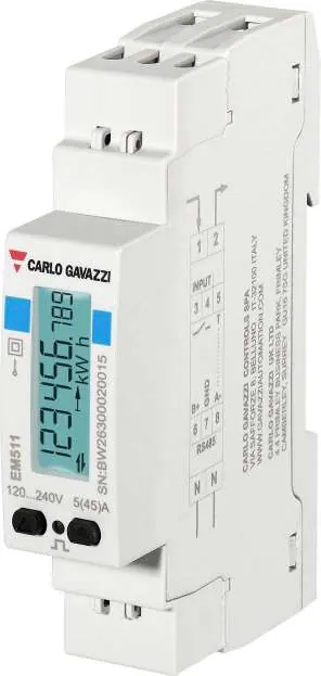
The Danfoss EM511 is a 1-phase energy analyzer designed for low-voltage switchboards. It supports systems up to 240 V L-N and currents up to 45 A. Key features include Modbus RTU communication, a digital input for remote control or reset, and a backlit LCD display. Ensure all electrical connections are performed by qualified personnel according to local regulations.
Description and Applications
The device monitors energy consumption, electrical variables (V, A, W, PF, Hz), and harmonic distortion. It is suitable for monitoring single machines or specific loads to identify malfunctions early and plan maintenance. It can also serve as a data source for control actions in photovoltaic installations with energy storage.
Installation and Wiring
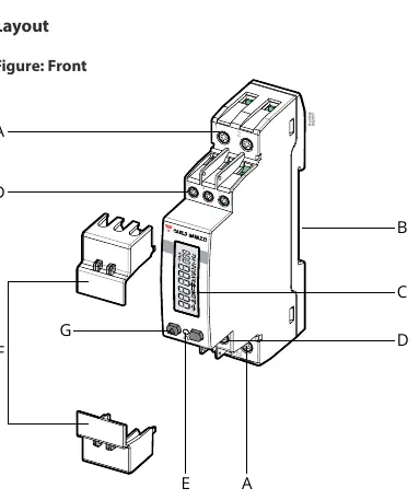
The device is designed for DIN rail mounting. Ensure the power supply is disconnected before installation.
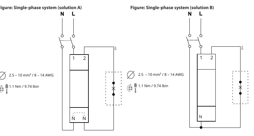
- Measurement Inputs: Use 2.5 – 10 mm² (8 – 14 AWG) wires. Tighten terminals to 1.1 Nm.
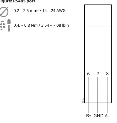
- Communication/Digital Input: Use 0.2 – 2.5 mm² (14 – 24 AWG) wires. Tighten terminals to 0.4 – 0.8 Nm.
- Connection Diagrams: Refer to the connection diagrams for Single-phase system (solution A or B) depending on your specific setup.
Data Communication
The EM511 features a Modbus RTU RS485 port for integration into systems like the AK-SM 800A.
- Protocol: Modbus RTU.
- Connection: 2-wire, multidrop, bidirectional.
- Configuration: Address (1-247), Baud rate (9.6/19.2/38.4/115.2 kbps), Parity (None/Even).
- Wiring: Connect B+, GND, and A- terminals. Note that for AK-SM 800A, Modbus A+ connects to B+ and Modbus B- connects to A-.
Digital Input
The digital input supports functions such as remote status monitoring, tariff management, and partial meter reset/start/pause. It is a free contact type input.
Technical Specifications
- Voltage: 120 – 240 V L-N.
- Current: Base current 5 A, Maximum current 45 A, Start-up current 0.02 A.
- Frequency: 50/60 Hz.
- Protection: IP40 (front), IP20 (terminals).
- Operating Temperature: -25 to +55 °C.
Manufacturer information
Danfoss A/S
Practical help
Common problems
Communication failure with Modbus
Verify wiring polarity (A+ to B+, B- to A- for AK-SM 800A) and ensure baud rate/parity settings match the master device.
Incorrect energy readings
Check the current direction and ensure the correct connection solution (A or B) is used for your single-phase system.
Display not powering on
Verify that the supply voltage is within the 120-240 V AC range and that connections are secure.
Before use
- Verify supply voltage is 120-240 V AC.
- Ensure load current does not exceed 45 A.
- Check that DIN rail space is sufficient.
- Prepare 2.5-10 mm² wires for measurement inputs.
- Prepare 0.2-2.5 mm² wires for communication and digital inputs.
- Ensure Modbus master settings match the device configuration.
Specs in practice
- Rated voltage
- 120-240 V L-N operating range.
- Protection degree
- IP40 for the front panel, IP20 for terminals.
- Communication
- Modbus RTU RS485 for remote data collection.
Images and diagrams
- RS485 port diagram shows the B+, GND, and A- terminal layout.
- Single-phase system diagrams illustrate the correct wiring for L and N lines.
- Digital input diagram shows the connection for external control switches.
Model compatibility
- Compatible with AK-SM 800A refrigeration control systems.
- Requires Modbus RTU master for remote data access.

Manual page author
Michael Turner
Technical manual editor
Reviews PDF manuals for structure, safety notes, and practical product details so readers can find the right information quickly.