Power / Power Inverters
User Manual for RS Pro 10...150A AC CCT2 Current Transformer
Quick guide for the RS Pro 10...150A AC CCT2 Current Transformer. Includes installation instructions, connection diagrams, technical specifications, and mounting details.
Table of contents
Manual images
Click an image to enlargeQuick guide from the manual
The RS Pro CCT2 Current Transformer is designed for reliable measurement of AC current (50/60Hz) in network analysis and monitoring applications. It provides a proportional 4-20 mA or 0-5/10 V DC output. This document outlines the installation, wiring, and technical specifications required for proper operation.
Technical Parameters
- Measuring Range: 0 to 150A
- Frequency Range: 50/60 Hz
- DC Output: 4-20 mA or 0-5/10 V DC
- Accuracy: Class 0.5 (IEC 60688)
- Auxiliary Voltage: 24 V DC, ±15%
- Isolation Test Voltage: 3kV AC, 50 Hz, 2 Seconds (Input terminals vs Housing)
- Protection Class: IP20
- Operating Temperature: 0°C to +70°C (0-95% rH, non-condensing)
- Thermal Nominal Continuous Rated Current: 1.2 x In
Connections
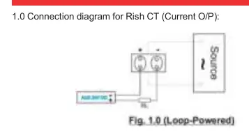
The device features wire-sealable terminal covers and uses M4 screws with a self-lifting clamp strap assembly. To connect, insert the output wires into the terminals and tighten them securely using a screwdriver. Refer to the specific connection diagrams for Current Output (4-20mA) and Voltage Output (0-5/10V) configurations.
Mounting
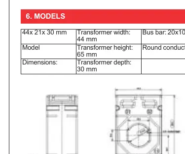
For installation, use the wall mounting clamps provided with the CCT2 unit. Ensure the primary conductor passes through the transformer aperture correctly. The device supports bus bars up to 20x10 mm or round conductors up to 21 mm in diameter.
Scope of Supply
- CCT2 Current Transformer
- Wall Mounting Clamp
- Test Certificate
- Operating Instruction Manual
Manufacturer information
RS PRO
Practical help
Common problems
Output signal is incorrect or unstable
Verify that the burden resistance is within limits. For Current O/P: R=600 max @24V Aux. B or R=300 max @15V Aux. B. For Voltage O/P: R=1M min (for 10A-20A) or R=200k min (for 100A-150A).
Device not powering on
Ensure the auxiliary voltage is 24V DC ±15%.
Before use
- Verify the primary current range (10-150A) matches your application requirements.
- Ensure the auxiliary power supply is 24V DC.
- Check that the conductor size fits the aperture (21mm round or 20x10mm bus bar).
- Confirm the required output type (4-20mA or 0-5/10V DC) matches your system input.
- Ensure the environment is within the operating temperature range (0°C to +70°C).
Specs in practice
- Accuracy Class 0.5
- Indicates high precision measurement, suitable for industrial monitoring.
- Isolation 3kV AC
- Ensures electrical safety by isolating the primary conductor from the output terminals.
- Burden Resistance
- The maximum or minimum load resistance allowed on the output to maintain signal accuracy.
Images and diagrams
- The connection diagrams illustrate the wiring path for both Current Output (4-20mA) and Voltage Output (0-5/10V) configurations.
- The dimension diagram provides the physical footprint (44x21x30 mm) and aperture sizes for conductors.
Model compatibility
- Compatible with bus bars up to 20x10mm.
- Compatible with round conductors up to 21mm diameter.

Manual page author
Michael Turner
Technical manual editor
Reviews PDF manuals for structure, safety notes, and practical product details so readers can find the right information quickly.