Industrial / Energy Monitoring
Installation Manual for Janitza UMG 103-CBM Power Analyser
Quick guide for the Janitza UMG 103-CBM Power Analyser. Includes installation steps, wiring diagrams for voltage and current measurement, RS485 configuration, and troubleshooting.
Table of contents
Manual images
Click an image to enlargeQuick guide from the manual
The Janitza UMG 103-CBM is a universal measurement device for low-voltage distribution systems. This manual covers the installation, electrical connection, and configuration of the device. Ensure all safety protocols are followed, as the device involves dangerous electrical voltages.
Safety instructions
- Qualified personnel only: Installation and operation must be performed by personnel with electrical training.
- Electrical hazard: The device carries dangerous voltages. Always render the system voltage-free before starting work.
- Grounding: Earth the device at the ground wire connection if available. Earth the secondary windings of current transformers.
- Proper use: Intended for installation in switch cabinets and small installation distributors. Not for use in vehicles or environments with hazardous substances.
Installation and mounting
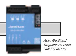
The device is designed for mounting on a 35 mm DIN rail (DIN EN 60715). It can be installed in any position. Forced ventilation is not required.
Connecting supply voltage
The device derives its supply voltage from the measurement voltage (L1-N, L2-N, L3-N). It requires at least 100 Veff in at least one phase for operation. Ensure the supply voltage is protected with a UL/IEC approved circuit breaker or fuse.
Voltage and current measurement
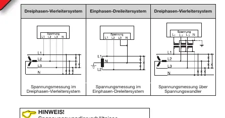
- Voltage: Measures L-N up to 277 V and L-L up to 480 V. Voltages exceeding rated network voltages must be connected via a voltage transformer.
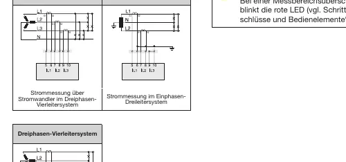
- Current: Only approved for measurement via current transformers (../1 A or ../5 A). The standard ratio is set to 5/5 A.
- Warning: Never operate current transformers with an open secondary circuit, as this causes high voltage peaks. Short-circuit unloaded transformers.
RS485 communication
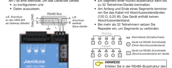
The device uses an RS485 interface with Modbus RTU protocol for configuration and data readout. In an RS485 bus structure, connect devices in a master-slave principle. Terminate the cable at the start and end of a segment with 120 Ohm resistors.
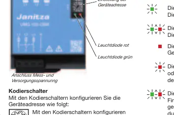
Controls and LED indicators
The device features coding switches to set the device address (01-99). LED indicators provide status updates:
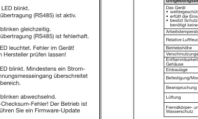
- Green LED steady: Operational.
- Green LED flashing: Data transfer active.
- Red LED steady: Device fault.
- Red LED flashing: Measurement range exceeded.
- Alternating LEDs: Firmware checksum error.
Troubleshooting
If the device is not functioning correctly, check the following:
- No LED lights: Check external fuses or potential device defect.
- Incorrect current/voltage readings: Verify phase connections and transformer ratio programming.
- No connection: Verify RS485 address and protocol settings.
Practical help
Common problems
No LED lights
Check if the external fuse for the supply voltage has tripped. If the fuse is intact, the device may be defective.
Measured current or voltage is too large or too small
Check if the measurement is in the wrong phase, verify the transformer ratio programming, or check if the measurement range has been exceeded.
No connection to the device
Verify that the RS485 device address is correct and the correct protocol is selected.
Before use
- Ensure the system is voltage-free before starting installation.
- Verify that voltage and frequency match the rating plate.
- Install a UL/IEC approved circuit breaker or fuse for the voltage measurement inputs.
- Ensure current transformers are not operated with an open secondary circuit.
- Ground the device and the secondary windings of current transformers.
- Install the GridVis software on the PC for configuration.
Specs in practice
- Measuring range (Current)
- 0.005 to 6 Arms.
- Overvoltage category
- 300 V CAT III for voltage measurement; 300 V CAT II for current measurement.
- RS485 Protocol
- Modbus RTU/Slave with automatic baud rate detection.
Images and diagrams
- Wiring diagrams illustrate connections for 3-phase 4-conductor and 1-phase 3-conductor systems.
- RS485 bus structure requires termination resistors (120 Ohm) at the start and end of the segment.
Model compatibility
- Suitable for TN and TT networks.
- Not intended for installation in vehicles.
- Requires current transformers for current measurement.

Manual page author
Emily Carter
User documentation editor
Prepares concise manual descriptions and highlights the most useful setup, operation, and maintenance information for readers.