Industrial / Energy Monitoring
Janitza RCM 202-AB Residual Current Measurement Device Installation Instructions
Installation and setup guide for the Janitza RCM 202-AB residual current measurement device. This guide covers wiring, Modbus configuration, analog output setup, and technical specifications for monitoring residual currents in TN and TT...
Quick answers from the manual
Quick answer
- The RCM 202-AB is a two-channel residual current measurement device for monitoring main distribution boards up to 20 A in TN and TT systems. p. 1
Key actions
- Mounting on DIN rail p. 2
- Connecting current transformers p. 1, 2
First start
- Connect power and wait for initialization p. 2
Problems and fixes
Status LED flashes red
Check for short circuit or wire break on the transformers.
p. 1Technical specifications
| Parameter | Value | Meaning | Pages |
|---|---|---|---|
| Supply voltage | AC 90 ... 230 V | Operating voltage range | p. 2 |
| Measurement channels | 2 | Number of connectable transformers | p. 2 |
Where to find it in the PDF
- Installation and Safety p. 1
- Technical Data and Connection p. 2
Table of contents
Manual images
Click an image to enlargeQuick guide from the manual
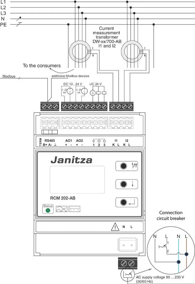
The RCM 202-AB is a two-channel residual current measurement device designed for monitoring main distribution boards up to 20 A in TN and TT systems. Installation must be performed by qualified electro-technical personnel. Ensure the power supply is disconnected before mounting and that the PE conductor is not routed through the current measurement transformer.
Device overview
The device features a display, operating keys, status LED, and various connection interfaces including Modbus (RS485), analog outputs (4-20 mA), and digital outputs. The device is designed for mounting on a 35 mm top hat rail (DIN EN 60715).
Installation
Mounting: Snap the device onto a 35 mm top hat rail and ensure a tight fit.
Wiring: Connect the current measurement transformers to the I1 and I2 inputs. Observe the K and L connections. Connect the power supply to the N and L terminals (AC 90-230 V). If the device is the first or last participant in a Modbus line, set the termination resistor (120 Ohm) using the TERM switch.
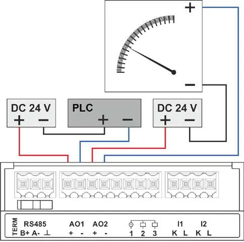
Outputs: Connect analog and digital outputs as required. Note that analog outputs require a separate DC 12-24 V power supply and must be used with galvanically isolated inputs to avoid measurement errors.
Commissioning
After connecting the power supply, the status LED will flash green. Initialization takes up to 60 seconds. The device is ready for operation once the measured values appear on the display. If the status LED flashes red, check for wire breaks or short circuits on the connected transformers.
Technical data
The device operates on AC 90-230 V (50/60 Hz) and consumes approximately 8 W. It supports Modbus RTU communication via RS485. The analog outputs provide a 4-20 mA signal. The device is rated for operation in temperatures between -5°C and +55°C.
Practical help
Common problems
Status LED flashes red
Indicates a short circuit or wire break on the connected current measurement transformers. Check the wiring.
Measurement errors
Ensure only ONE analog measurement circuit is used per device and that inputs are galvanically isolated.
Initialization takes longer than 60 seconds
Initialization may take longer if the transformer measures residual currents during the startup process.
Before use
- Ensure installation is performed by qualified electro-technical personnel.
- Disconnect power supply before mounting and connecting.
- Verify current measurement transformers are installed on the cables to be monitored.
- Ensure the PE conductor is NOT routed through the current measurement transformer.
- Check that the Modbus termination resistor is set correctly if the device is the first or last in the bus line.
- Verify that analog output connections are galvanically isolated.
Specs in practice
- Supply voltage
- AC 90 ... 230 V, 50/60 Hz.
- Measurement channels
- 2 channels for current measurement transformers.
- Analog outputs
- Two 4 ... 20 mA interfaces requiring separate DC 12-24 V power.
Images and diagrams
- Wiring diagram shows connection of current transformers to I1/I2 inputs.
- Modbus connection requires termination resistor (120 Ohm) for end-of-line devices.
- Analog outputs require separate DC 12-24V power supply.
Model compatibility
- Compatible with current measurement transformers with transformation ratios like 600:1 or 700:1.
- Designed for TN and TT systems (grounded AC systems).

Manual page author
Michael Turner
Technical manual editor
Reviews PDF manuals for structure, safety notes, and practical product details so readers can find the right information quickly.