General / Other Manuals
Juniper 100G Optical Transceivers and Cables User Guide
Comprehensive guide for Juniper 100G optical transceivers and cables, covering specifications, installation, maintenance, and technical overviews.
Table of contents
Manual images
Jump to the sectionOverview of 100G Optical Transceivers
Juniper 100G optical transceivers are essential components for high-speed data transmission in modern network environments, including data centers, metro, and core networks. These modules support data rates of 100 Gbps and are available in various form factors such as CFP, CFP2, QSFP28, SFP56-DD, and SFP-DD. The choice of transceiver depends on specific requirements like reach, fiber type, and power consumption.
Technical Specifications and Modulation
100G transceivers utilize advanced modulation techniques to achieve high capacity. Common schemes include Pulse Amplitude Modulation 4-level (PAM4) for shorter-reach, cost-sensitive applications, and Non-Return-to-Zero (NRZ) for longer reaches. Forward Error Correction (FEC) is often employed to maintain signal integrity, especially with PAM4 modulation. The architecture typically involves a host platform, electrical interfaces, Digital Signal Processing (DSP), and optical components like lasers and photo-detectors.
Installation and Maintenance
Juniper transceivers are hot-swappable, allowing for installation and removal without powering down the device. Proper handling is critical to ensure performance and longevity. Always use an ESD wrist strap during installation to prevent electrostatic discharge damage. When not in use, ports and transceiver connectors must be covered with dust caps or rubber safety caps to prevent contamination and laser exposure. Fiber-optic cables should be managed to avoid exceeding their minimum bend radius, which can cause signal degradation.
Cable Types and Breakout Capability
Juniper offers both Direct Attach Copper (DAC) cables and Active Optical Cables (AOC). DAC cables are ideal for ultra-short-range connections, while AOCs are better suited for longer distances due to their fiber-optic architecture. Many 100G ports support breakout capability, allowing a single high-speed port to be split into multiple lower-speed links (e.g., 4x25G or 2x50G) using appropriate breakout cables. This flexibility is vital for optimizing network resources in flat data center architectures.
Safety and Best Practices
Safety is paramount when working with optical equipment. Never look directly into fiber-optic transceivers or cable ends, as they emit laser light that can cause eye damage. Always verify optical power levels before deployment, particularly when using APD-based transceivers, to avoid damage from excessive input power. Regular cleaning of fiber-optic connections using approved cleaning kits is recommended to prevent signal loss due to dust or oil.
Manufacturer information
Juniper Networks
Practical help
Common problems
Intermittent signal or loss of light
Clean the transceiver canal and cable connector tip using an approved fiber-cleaning device.
Thermal damage to host equipment
Ensure only qualified Juniper-supplied transceivers are used, especially for high-power consumption modules.
Transceiver not recognized or operational
Wait at least 6 seconds after insertion for the interface to initialize and display operational commands.
Physical damage to fiber-optic cables
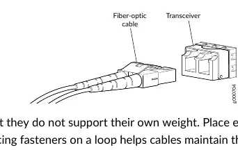
Ensure cables are not bent beyond their minimum bend radius and do not support their own weight.
Before use
- Wear an ESD wrist strap connected to a proper ESD point.
- Verify the transceiver is compatible with your specific Juniper device.
- Ensure the port is free of dust and covered if not in use.
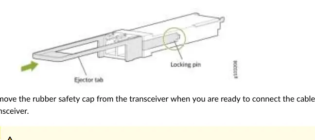
- Check that the transceiver has a rubber safety cap if not immediately connecting a cable.
- Label cables before disconnection to ensure correct reconnection.
Specs in practice
- Breakout Capability
- Ability to split a high-speed port into multiple lower-speed logical ports.
Images and diagrams
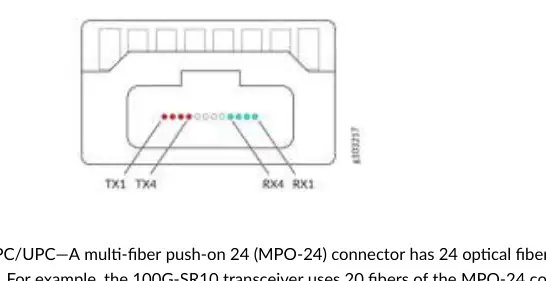
- Figure 8: MPO-12 connector showing lane allocation for transmit and receive channels.
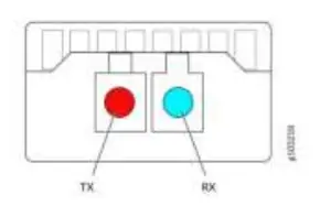
- Figure 10: Duplex LC connector showing red (TX) and blue (RX) channel allocation.
- Figure 11: Illustration of a 100G DAC cable assembly.
- Figure 12: Illustration of a 100G AOC cable assembly.
- Figure 14: Diagram showing the installation process of a QSFP28 transceiver including the ejector tab.
Model compatibility
- CFP and CFP2 modules do not support breakout capability.
- SFP-DD is backward compatible with SFP28, SFP+, and SFP modules.
- QSFP28 ports are backward compatible with QSFP+ ports in some configurations.
- Third-party transceivers are not supported by JTAC and may cause host damage.

Manual page author
Emily Carter
User documentation editor
Prepares concise manual descriptions and highlights the most useful setup, operation, and maintenance information for readers.