Automotive / Utility Vehicle Accessories
Installation Manual for KFI 106180-AP V Plow Dash Rocker Switches
Installation guide for KFI 106180-AP V Plow Dash Rocker Switches. Includes wiring diagrams, step-by-step installation instructions, and relay mounting guidelines for your V-plow setup.
Table of contents
Manual images
Click an image to enlargeQuick Installation Guide
This guide provides instructions for installing the KFI 106180-AP V Plow Dash Rocker Switches. The installation involves connecting the main actuator harnesses to the battery, splicing into a keyed power source, and mounting the relays. Ensure all wires are routed away from sharp or hot objects to prevent damage.
Kit Components
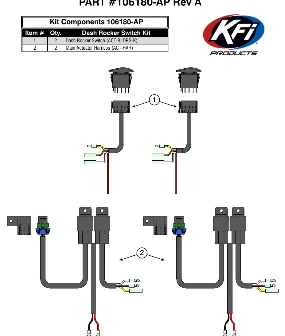
- Dash Rocker Switch (ACT-BLDRS-K): Quantity 2
- Main Actuator Harness (ACT-HAR): Quantity 2
Wiring Instructions
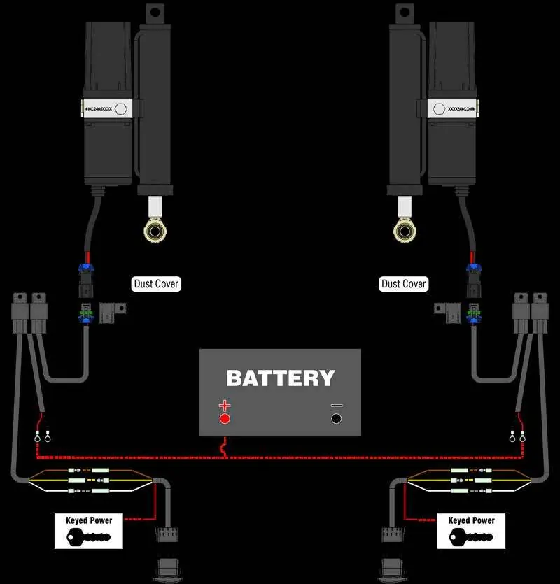
- Connect the Red and Black wires from both Main Actuator Harnesses (2A and 2B) to the battery. Connect Red wires to the Positive (+) terminal and Black wires to the Negative (-) terminal.
- Splice the end of the red wires from both Dash Rocker Switches (1A and 1B) into a power source controlled by the ignition (Keyed Power). Use a test light to identify a wire that receives power only when the key is in the ON position.
- Connect the Brown, Yellow, and White wires from one Dash Rocker Switch (1A) to one Main Actuator Harness (2A) as follows: Brown (Female) to Brown (Male), Yellow (Male) to Yellow (Female), and White (Female) to White (Male).
- Repeat the connection process for the second Dash Rocker Switch (1B) and the second Main Actuator Harness (2B).
Mounting and Maintenance
Find a clean and dry location to mount the relays. Ensure the chosen location provides sufficient clearance from all metal components and keeps the relays away from sharp or hot objects. Drill a mounting hole if required and secure the relays using zip ties or self-tapping screws.
Use zip ties to secure the dust covers on the Main Actuator Harnesses to the front of the machine. Ensure they are positioned so the plugs going to the actuator can be easily connected when the plow is not in use.
Pro-V Plow Hand Remote Upgrade
KFI offers a V-plow hand remote that allows users to control the plow with pre-programmed settings and full articulation of each actuator from a single remote. This system can be integrated by installing a Hand Remote Harness, which connects to the Main Actuator Harnesses and the existing Dash Rocker Switches. Contact your local dealer or KFI for more information.
Practical help
Common problems
Plow not responding
Verify battery connections and ensure the keyed power source is active when the ignition is ON.
Wire damage or short circuit
Ensure all wires are routed away from sharp edges and hot engine components. Do not crimp or cut wires during installation.
Switch connection issues
Verify that the Brown, Yellow, and White wires are correctly matched (Female to Male) between the switch and the harness.
Before use
- Verify all kit components (2 switches, 2 harnesses) are present.
- Identify a keyed power source using a test light.
- Ensure sufficient clearance for relay mounting.
- Have zip ties and self-tapping screws ready for mounting.
- Read and understand all instructions before beginning.
Specs in practice
- Main Actuator Harness
- The primary wiring assembly connecting the switch to the plow actuator.
Images and diagrams
- Figure 1 illustrates the complete wiring schematic connecting the battery, keyed power, switches, and actuators.
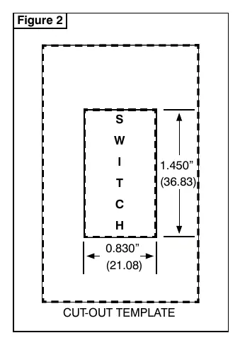
- Figure 2 provides the cut-out template dimensions (1.450" x 0.830") for mounting the switches.
Model compatibility
- Compatible with KFI Pro-V plow systems.
- Can be upgraded with the KFI Pro-V Plow Hand Remote.

Manual page author
Michael Turner
Technical manual editor
Reviews PDF manuals for structure, safety notes, and practical product details so readers can find the right information quickly.