Automotive / Electrical Accessories
Installation Guide for KFI 106180-APH V Plow Hand Remote
Complete installation guide for the KFI 106180-APH V Plow Hand Remote. Includes wiring diagrams, mounting instructions for the panel plug, and electrical connection steps for your winch system.
Table of contents
Manual images
Click an image to enlargeQuick Guide from the Manual
This document provides installation instructions for the KFI 106180-APH V Plow Hand Remote. It covers wiring, mounting the panel plug, and connecting the system to your winch and battery. Ensure all components are present before starting. Always keep wires away from sharp or hot objects and be careful not to crimp or cut wires during installation.
Kit Components
- 1: Hand Remote (ACT-VHR)
- 2: Hand Remote Harness (ACT-HR-HAR)
- 3: Main Actuator Harness (ACT-HAR) - 2 included
Installation Instructions
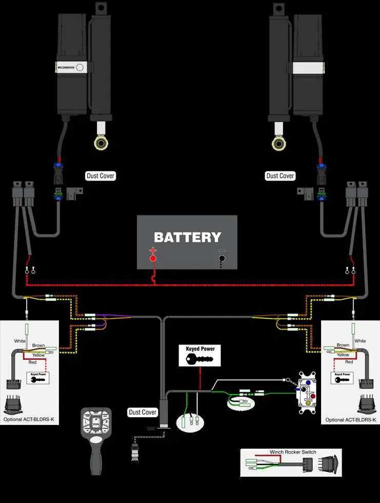
- Connect the Red and Black wires from the Main Actuator Harnesses (3A and 3B) to the battery. Connect Red to the Positive (+) terminal and Black to the Negative (-) terminal.
- Splice the end of the red wire from the Hand Remote Harness (2) into a power source controlled by the ignition (Keyed Power). Use a test light to identify a wire that receives power only when the key is in the ON position.
- Connect the green and black wires on the Hand Remote Harness (2) to the green and black wires on the winch contactor. Connect the white wire to the negative (-) post on the contactor.
- Connect the Brown and Yellow wires from the Hand Remote Harness (2) to the Main Actuator Harness (3A): Brown (Female) to Brown (Male) and Yellow (Male) to Yellow (Female).
- Connect the Purple and Orange wires from the Hand Remote Harness (2) to the Main Actuator Harness (3B): Purple (Female) to Brown (Male) and Orange (Male) to Yellow (Female).
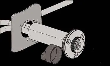
- Choose a location to mount the 8-pin panel plug on the Hand Remote Harness (2). Drill a 3/4" (19mm) hole. Secure the plug using the supplied screws, being careful not to overtighten.
- Mount the relays in a clean, dry location with sufficient clearance from metal components. Secure with zip ties or self-tapping screws.
- Use zip ties to secure the dust covers on the Main Actuator Harnesses (3A and 3B) to the front of the machine.
Wiring and Electrical Connections
Note that your winch switch or contactor may have different colors or connections. On the Hand Remote Harness (ACT-HR-HAR), the standard color coding is: Green = Winch IN, Black = Winch OUT, White = Ground, and Red = Keyed Power. If you are using a non-KFI winch, use the provided connectors to tap into the IN and OUT wires on the winch contactor.
The Hand Remote Harness has extra connection points for additional switches. If these connections are not used, wrap the ends in electrical tape.
Maintenance and Storage
When the Hand Remote (1) is not in use, always cover the panel plug on the Hand Remote Harness (2) with the dust cover to keep it clean. Store the Hand Remote in a safe location.
Practical help
Common problems
Non-KFI winch wiring
Use the provided connectors to tap into the IN and OUT wires on the winch contactor.
Extra harness connections
If you have connections on the Hand Remote Harness that are not going to be used, wrap those ends in electrical tape.
Wiring color mismatch
Your winch switch/contactor may have different colors. Use a test light to verify the correct wires for Winch IN, Winch OUT, Ground, and Keyed Power.
Before use
- Verify all kit components (Remote, Harnesses) are present.
- Identify a keyed power source using a test light.
- Ensure you have a 3/4" (19mm) step bit for drilling the panel plug hole.
- Have electrical tape and zip ties ready for securing wires.
- Ensure the mounting location for relays is clean, dry, and away from hot/sharp objects.
Specs in practice
- Panel Plug Hole
- Requires a 3/4 inch (19mm) diameter hole.
Images and diagrams
- Figure 1: Wiring diagram showing connections between the Hand Remote, Main Actuator Harnesses, Battery, and Winch Contactor.
- Figure 2: Illustration of the panel plug mounting process into the dash.
- Figure 3: Template for drilling the 3/4 inch hole for the panel plug.
Model compatibility
- Designed to be compatible with KFI and other brand winches.
- If additional controls are wanted for the V Plow, you can add (2x) Dash Rocker Switches (ACT-BLDRS-K).

Manual page author
David Miller
Documentation analyst
Organizes user manual content into clear summaries, with attention to model details, product context, and everyday usability.