Tools / Power Tools
Instruction Manual for OFITE 120-20-A Automated Curing Chamber
Comprehensive user guide for the OFITE 120-20-A Automated Curing Chamber, covering setup, test operation, touch-screen interface configuration, maintenance procedures, and troubleshooting.
Table of contents
Manual images
Jump to the sectionQuick guide from the manual
The OFITE 120-20-A Automated Curing Chamber is designed for preparing cement specimens for compressive strength tests under downhole temperatures and pressures. Key operations include preparing cement molds, setting test profiles via the touch screen, and performing routine maintenance on filters and valves.
Setup
1. Remove the instrument from the crate and ensure the PRESSURE RELEASE valve is closed (clockwise).
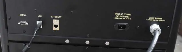
2. Connect compressed air or Nitrogen, water supply, and drain lines (all 1/4" NPT) to the back of the unit.
3. Connect to a 220V power source. A backup power port is available for an Uninterruptable Power Supply (UPS) to keep electronics active during power loss.
4. Turn the MAIN POWER switch ON.
Operation
Starting a Test:
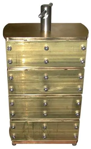
- Loosen the twelve set screws on the cell cap and remove it.
- Place the prepared cement mold into the cell, ensuring the thermocouple port is centered.
- Lubricate the sealing ring and threads with high-temperature grease.
- Tighten the cell cap by hand, then tighten the twelve set screws in a cross pattern using a torque wrench (first to 90 inch-pounds, then to 180 inch-pounds).
- Insert the thermocouple, set the FILL/DRAIN switch to FILL, and wait for water to flow from the thermocouple connection before tightening the fitting.
- Set HEAT, COOL, and PUMP switches to AUTO and start the test via the display.
Ending a Test:
- If the 'Stop At End' option is off, touch 'Stop Test', set HEAT to OFF, and COOL to ON.
- Once the temperature is below 180°F (80°C), set the PUMP to OFF.
- Slowly open the PRESSURE RELEASE valve (counterclockwise) only after the temperature is below 200°F (93°C).
- Set FILL/DRAIN to DRAIN to purge water, then remove the specimens.
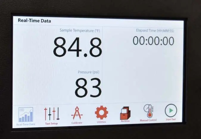
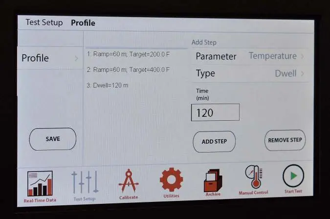
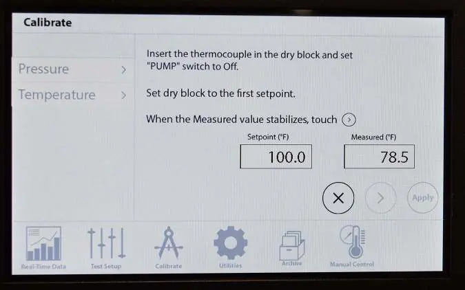
Onboard Display
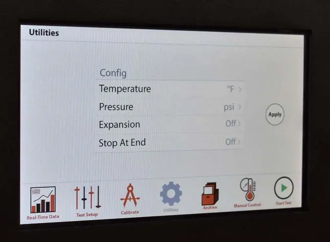
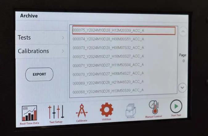
The touch screen allows for test configuration, manual control, and data archiving. Use the 'Test Setup' screen to create ramp, step, or dwell profiles. The 'Utilities' screen allows configuration of units (°F/°C, psi/MPa) and the 'Stop At End' feature. Data and calibrations can be exported to a FAT32-formatted USB drive via the 'Archive' screen.
Maintenance
- Water Filter: Clean every three months (or more frequently depending on water quality).
- Air Filter: Periodically empty accumulated moisture from the clear chamber.
- Outlet Filter: Clean monthly to remove cement residue.
- Check Valve: Clean or replace if dirty to ensure proper air/water flow.
- Regulators: Main pump regulator should be 80-100 psi; back pressure regulator should be 70-80 psi.
Manufacturer information
OFI Testing Equipment, Inc.
Practical help
Common problems
No power to the machine
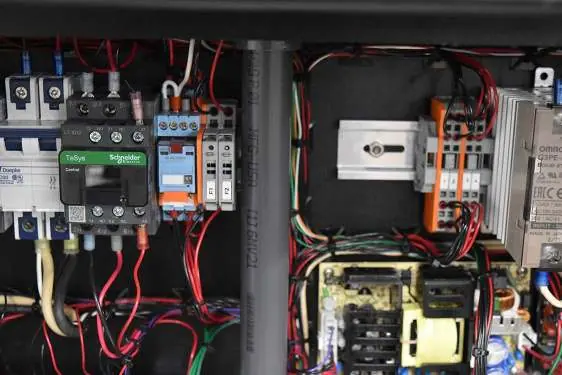
Ensure the main power cord is firmly plugged in and check the F1 and F2 fuses.
Unit is not heating
Ensure the HEAT switch is set to AUTO or MANUAL. Note that the heater will not function while on battery backup.
Pressure will not reach setpoint
Adjust the supply regulator to 80-100 psi or clean/replace the inlet check valve.
Pressure rises above setpoint
Adjust the pressure release regulator to 70-80 psi or clean the clogged outlet filter.
Before use
- Ensure PRESSURE RELEASE valve is closed (clockwise).
- Verify all switches are in OFF or AUTO position.
- Check that air, water, and drain lines are connected.
- Lubricate sealing ring and threads with high-temperature grease.
- Tighten cell cap set screws in a cross pattern to 180 inch-pounds.
- Ensure thermocouple is properly inserted and tightened.
Specs in practice
- Maximum Temperature
- 400°F (204°C)
- Maximum Pressure
- 5,000 psi (34.5 MPa)
- Power Requirements
- 220 Volts, 50/60 Hz, 30 Amp
Images and diagrams
- The control panel features switches for FILL/DRAIN, LVDT, HEAT, COOL, PUMP, and MAIN POWER.
- The rear panel includes ports for Serial, USB, Ethernet, Backup Power, and Main Power.
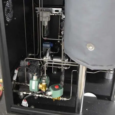
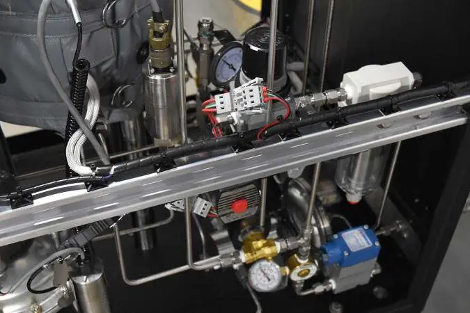
- Internal maintenance points include the water filter, air filter, outlet filter, and pressure regulators.
Model compatibility
- Specimens must be prepared according to API Specification 10.
- USB drives for data export must be formatted in the FAT32 file system.
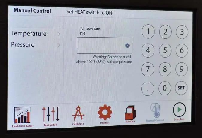
- Do not heat the cell above 190°F (88°C) without pressure.

Manual page author
Emily Carter
User documentation editor
Prepares concise manual descriptions and highlights the most useful setup, operation, and maintenance information for readers.