Tools / Power Tools
Instruction Manual for OFITE 115V Atmospheric Consistometer
Quick guide for the OFITE 115V Atmospheric Consistometer, covering setup, test cell loading, operation, calibration procedures, and annual maintenance.
Table of contents
Manual images
Jump to the sectionQuick guide from the manual
The OFITE Atmospheric Consistometer is designed to condition cement slurries according to API Specification 10. It operates at atmospheric pressure and features a dual-container design with microprocessor-controlled temperature and stirring at 150 RPM. This document provides essential procedures for setup, operation, and maintenance.
Setup
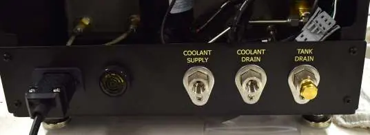
Place the unit near a water supply and drain. Connect the coolant supply and drain lines (1/4" NPT) to a 40 PSI water source. Fill the bath with approximately 2 gallons of mineral oil until the level reaches the red dot on the sight glass. Do not overfill. Connect the unit to a grounded and fused electrical supply.


Loading the Test Cells

- Prepare the cement slurry as specified in API Specification 10 and pour it into the slurry container.
- Insert the paddle into the test cell, ensuring the point is seated in the bottom hole.
- Place the lid on the test cell, sliding the torque shaft over the paddle end. Turn the lid clockwise until the pin engages with the slot in the paddle shaft.
- Lock the lid in place.
- Lower the test cell into the bath and secure it with the locking pins.
Operation
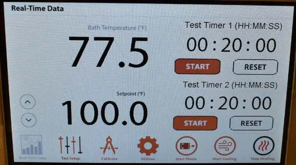
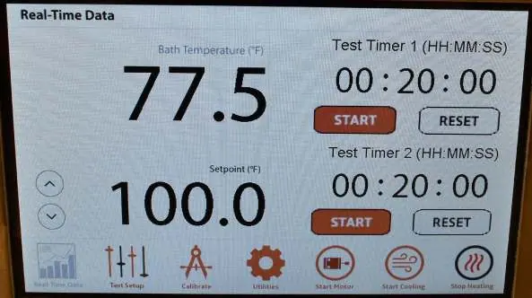
Begin the test within one minute of mixing the cement slurry. Use the touchscreen or control wheel to set the temperature. Start the motor and heater using the on-screen buttons. Set the test timers as needed. When the test is complete, stop the motor and heater, and activate cooling. If using water in the bath, keep the unit on until the temperature drops below 80°F (27°C) to allow the fan to remove moisture.
Calibration
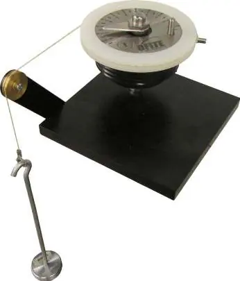
The torque head can be calibrated using the optional Calibrator Assembly (#120-75-30) and dead weights. Temperature verification is performed by comparing the screen reading to a reference thermometer at ambient temperature and at 190°F (88°C). Motor speed should be 150 RPM ± 15; adjust using the potentiometer speed control if necessary.
Maintenance
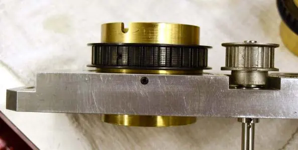
Inspect the drive belt and bearings annually. Disconnect power, remove the top cover, and loosen the drive plate to access components. Clean bearings with WD-40 or replace if they do not turn smoothly. Ensure the timing belt has 3/4" to 1" of slack. Check and clean the bath annually, replacing the mineral oil if contaminated. Replace broken stop pins immediately.
Manufacturer information
OFI Testing Equipment, Inc.
Practical help
Common problems
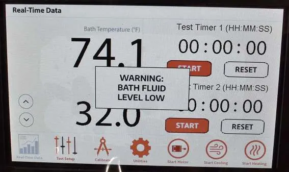
Alarm sounds and unit stops
Check if the oil level is low. Fill the bath with mineral oil and touch the alarm window to reset.
Rotational speed is not 150 RPM
Loosen the back panel screws, open the door, and adjust the potentiometer speed control clockwise to increase or counterclockwise to decrease speed.
Stop pin breaks
The pin is designed to break to protect the potentiometer if slurry is too thick. It must be replaced before the next test.
Before use
- Ensure the bath is filled with mineral oil to the red dot on the sight glass.
- Verify the unit is connected to a grounded and fused electrical supply.
- Ensure coolant supply is connected to a 40 PSI water source.
- Check that the paddle is correctly seated in the test cell.
- Verify the test begins within one minute of mixing the cement slurry.
Images and diagrams
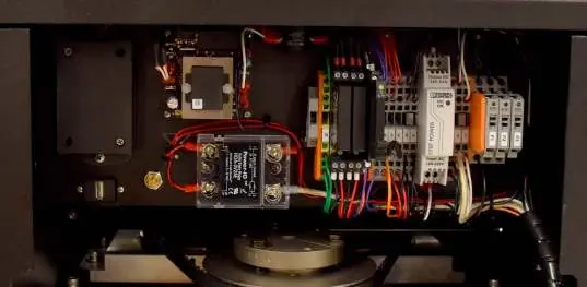
- The rear panel shows connections for Power, Alarm, Coolant Supply, Coolant Drain, and Tank Drain.
- The calibration setup uses a deadweight cord wrapped counterclockwise around the calibration ring.
- The drive plate assembly contains the rotators, belt, and main bearings requiring annual inspection.
Model compatibility
- Requires API Specification 10 compliant cement slurry preparation.
- 115V model (#120-75) requires 4.4 KVA power source.
- 220V model (#120-75-1) requires 2.2 KVA power source.

Manual page author
Emily Carter
User documentation editor
Prepares concise manual descriptions and highlights the most useful setup, operation, and maintenance information for readers.