Industrial / Signal Converters
User Manual for Onset 12-Bit 4-20 mA Input Adapter S-CIA-CM14
Quick guide for the Onset 12-Bit 4-20 mA Input Adapter (S-CIA-CM14). Learn how to mount the adapter, connect sensor cables, configure switched inputs for battery savings, and perform maintenance.
Table of contents
Manual images
Click an image to enlargeQuick guide from the manual
The Onset 12-Bit 4-20 mA Input Adapter (S-CIA-CM14) is designed for use with HOBO stations to measure 4-20 mA current loop outputs. It features a battery-saving switched input and a non-switched input, providing flexibility for various sensor types. This guide covers installation, wiring, and operation.
Specifications
- Measurement Range: 4-20 mA
- Accuracy: ± 0.1 mA (± 0.5% full scale) over -40°C to 75°C
- Resolution: ±4.93 µA
- Input Impedance: 124 Ω
- Switched Input: Max switch voltage 20 V; Max switch current 50 mA
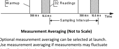
- Digital Filtering: Automatic with 32 readings/sample in 16.6 ms
Mounting
Use the included self-adhesive hook-and-loop tape to mount the adapter inside the logger enclosure. For multiple adapters, use the back of the logger enclosure door. For the HOBO Micro Station, the adapter can float freely inside the enclosure without tape.
Attaching Sensor Cables
Insert the cable through the opening at the bottom of the logger enclosure. Ensure you provide "drip loops" underneath the logger to prevent water from entering. Use the included cable tie to provide strain relief to the cable or individual wires.
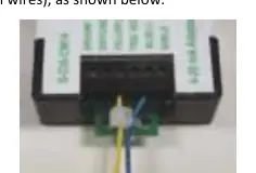
Sensor Input Connections
The adapter uses a 6-position screw terminal block for 16-30AWG wire. Pin definitions are as follows:
- Pin 1 (GROUND): Common connection.
- Pin 2 (SWITCHED YELL +): Yellow switched. Connects to Pin 3 once per sample to conserve external sensor battery. Max 20 V, 50 mA.
- Pin 3 (YELLOW +): Positive current input for sampling.
- Pin 4 (TRIG. SOURCE): Triggered source. Provides voltage from the logger battery to power or trigger external circuitry. Max 2.5 V, 1 mA.
- Pin 5 (BLUE -): Negative current input for sampling.
- Pin 6 (SHIELD): Connects cable shield for noise suppression.
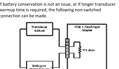
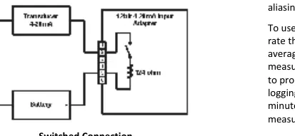
Operation and Switched Input
The adapter uses digital filtering and optional measurement averaging to improve accuracy. When using the switched input, the transducer is powered only during the warmup and sampling period, significantly extending battery life. Ensure your sensor has a warmup time of less than 300 ms if using the switched input.
Maintenance
The adapter is conformal coated for moisture protection. If installed correctly, it requires no maintenance. In unusually wet environments, if heavy condensation occurs, ensure the logger is properly sealed, move it to a better-ventilated location, or apply a spray lubricant like WD-40, LPS 1, or 711 to the terminal block to prevent corrosion.
Practical help
Common problems
Excessive moisture or condensation in the enclosure
Ensure the logger is properly sealed, move to a better-ventilated location, or apply a spray lubricant (e.g., WD-40) to the terminal block to prevent corrosion.
Sensor not powered correctly when using switched input
Verify the sensor has a warmup time of less than 300 ms and is capable of being powered from the 4-20 mA loop.
Inaccurate data readings
Verify accuracy annually against a known standard, such as a calibrated voltage source. Check for moisture or corrosion on the terminal block.
Before use
- Verify sensor warmup time is less than 300 ms if using switched input.
- Ensure sensor can be powered from the 4-20 mA loop.
- Check that the logger enclosure is properly sealed.
- Prepare 16-30AWG shielded cable for connections.
- Ensure the logger is stopped before inserting the adapter.
Specs in practice
- Switched Input
- A power-saving feature that powers the sensor only during the sampling interval.
- Digital Filtering
- Reduces noise by taking 32 readings per sample and averaging them.
- Measurement Averaging
- Optional setting to prevent aliasing if measurements fluctuate significantly.
Images and diagrams
- Wiring diagrams illustrate both switched and non-switched connection methods.
- Timing diagrams show the relationship between warmup, sampling, and digital filtering periods.
Model compatibility
- Designed for use with HOBO stations.
- Requires 16-30AWG wire for terminal connections.
- Compatible with 4-20 mA transducers.

Manual page author
Michael Turner
Technical manual editor
Reviews PDF manuals for structure, safety notes, and practical product details so readers can find the right information quickly.