Industrial / Signal Converters
Safety Manual for Turck IM(X)12-AI01-1I-1IU1R Isolating Transducer
Comprehensive safety manual for the Turck IM(X)12-AI01-1I-1IU1R isolating transducer. Includes installation, wiring diagrams, parameterization, safety function specifications, and proof test procedures.
Table of contents
Manual images
Click an image to enlargeQuick guide from the manual
This document provides essential safety and operational information for the Turck IM(X)12-AI01-1I-1IU1R isolating transducer. It is intended for trained and qualified personnel. The device is rated for SIL 2 (SC3) functional safety applications. Always ensure the device is registered online at www.turck.com/SIL before use.
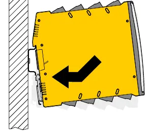
Installation and mounting
The device is designed for mounting on a DIN rail (TH35) according to EN 60715. Ensure the environment complies with the following ratings:
- Ambient temperature: -25 °C to 70 °C
- Storage temperature: -40 °C to 80 °C
- Air humidity: Max 95%
- Air pressure: 80 kPa to 110 kPa
Ensure sufficient heat dissipation and protect the device from dust, moisture, shock, and vibration. The device must be installed in a cabinet in an industrial field environment.
Wiring and connections
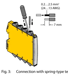
Connect cables according to the wiring diagrams provided in the manual. Use cables with a cross-section of 0.2 mm² to 2.5 mm² (rigid or flexible). When using stranded wires, fix the ends with ferrules.
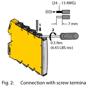
- Screw terminals: Insert stripped cable ends (7 mm) and fasten with a screwdriver (max. torque 0.5 Nm).
- Spring-type terminals: Push the opening lever with a screwdriver, insert the cable, and release.
Ensure the power supply is 10-30 VDC with a minimum power of 4 W.
Parameterization
The device is configured via DIP switches and a rotary coded switch. Configuration must not be performed while the unit is operating in a safety application.
- S1: Selects analog output type (current [A1A] or voltage [A2A]).
- S2: Sets A1D switching direction (under/over).
- S3: Sets A1D inverted mode (off/on).
- Rotary switch: Sets the threshold value from 5 mA to 20 mA in 1 mA steps.
Operation and maintenance
The device features LED indicators for status monitoring:
- PWR (Green): Device ready.
- B (Red flashing): Wire break at input.
- S (Red flashing): Short circuit at input.
- Rel (Yellow): Relay output energized.
- Inv (Yellow): Relay output inverted.
If the device enters a safe state due to an internal error, it must be replaced within 24 hours. Periodic proof tests must be executed according to the T1 interval to reveal dangerous faults.
Official resources from the manual
Practical help
Common problems
LED 'B' is flashing red
Indicates a wire break at the input. Check input wiring.
LED 'S' is flashing red
Indicates a short circuit at the input. Check input wiring.
Device not operating
Verify power supply is within 10-30 VDC range and wiring is secure.
Relay not switching as expected
Verify DIP switch settings (S2, S3) and rotary switch threshold value.
Before use
- Register the device online at www.turck.com/SIL.
- Ensure ambient temperature is between -25 °C and 70 °C.
- Verify power supply is 10-30 VDC.
- Use cables with 0.2-2.5 mm² cross-section.
- Tighten screw terminals to max 0.5 Nm.
- Perform a proof test after installation and parameterization.
Images and diagrams
- Wiring diagrams illustrate connections for E1 input, A1A/A2A outputs, and A1D relay output.
- DIP switch settings define analog output type, switching direction, and inverted mode.
- Rotary switch sets the threshold value from 5 mA to 20 mA.
Model compatibility
- Compatible with passive or active transmitters.
- Must be used in cabinets in an industrial field environment.
- The common alarm output is not part of the safety function.

Manual page author
David Miller
Documentation analyst
Organizes user manual content into clear summaries, with attention to model details, product context, and everyday usability.