Electronics / Monitors
Service Manual for Philips 107B7 17" CRT Color Monitor
Comprehensive service manual for the Philips 107B7 17" CRT monitor, including safety precautions, adjustment procedures, troubleshooting charts, mechanical disassembly instructions, and detailed spare parts lists.
Table of contents
Manual images
Jump to the sectionQuick guide from the manual
This service manual provides essential technical information for servicing the Philips 107B7 17" CDT Color Monitor. It is intended for qualified service personnel only. Important: Always use a separate isolation transformer when servicing this unit to prevent shock hazards. The manual covers safety precautions, adjustment procedures, troubleshooting, and mechanical disassembly.
Safety precautions
- Always wear shatter-proof goggles when handling the picture tube.
- The picture tube is designed to limit X-ray radiation; use only designated replacement tubes and adjust voltages to specified maximum ratings.
- Use only original manufacturer replacement parts to maintain safety characteristics.
- Perform an AC leakage current check on exposed metallic parts before returning the unit to the customer.
- The maximum operating high voltage for this chassis is 23.0kV ± 1kV.
Adjustment methods
Adjustments should only be performed when necessary, as most are factory-preset. Allow at least 30 minutes for warm-up before proceeding.
- B+ & HV Voltage: Connect a DC voltmeter between TP902 and ground; adjust VR902 to 140 ± 1 VDC. Set contrast and brightness to maximum, then adjust G2 voltage (600V for CPT CRT, 560V for LG CRT).
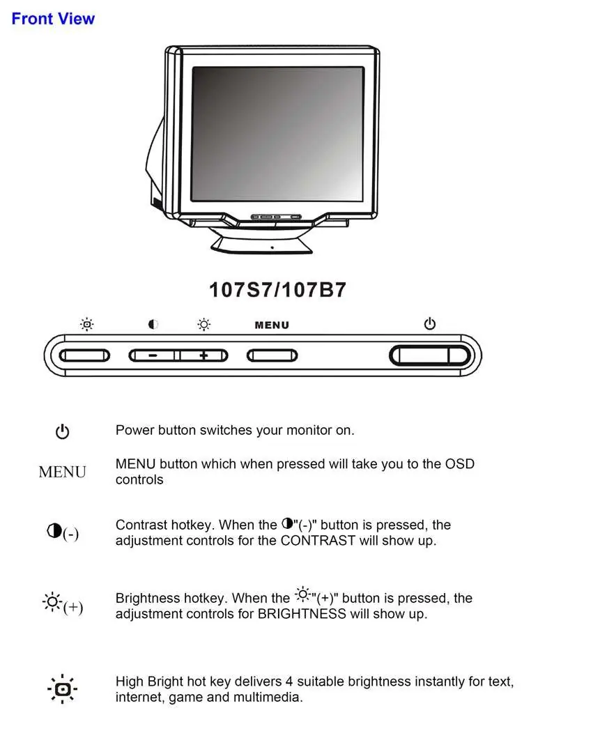
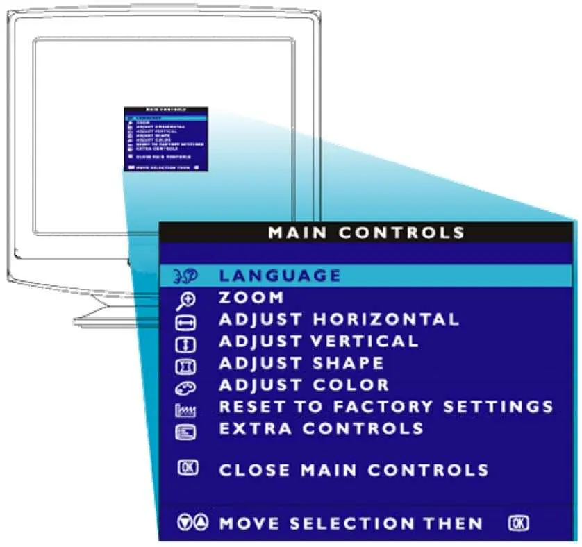
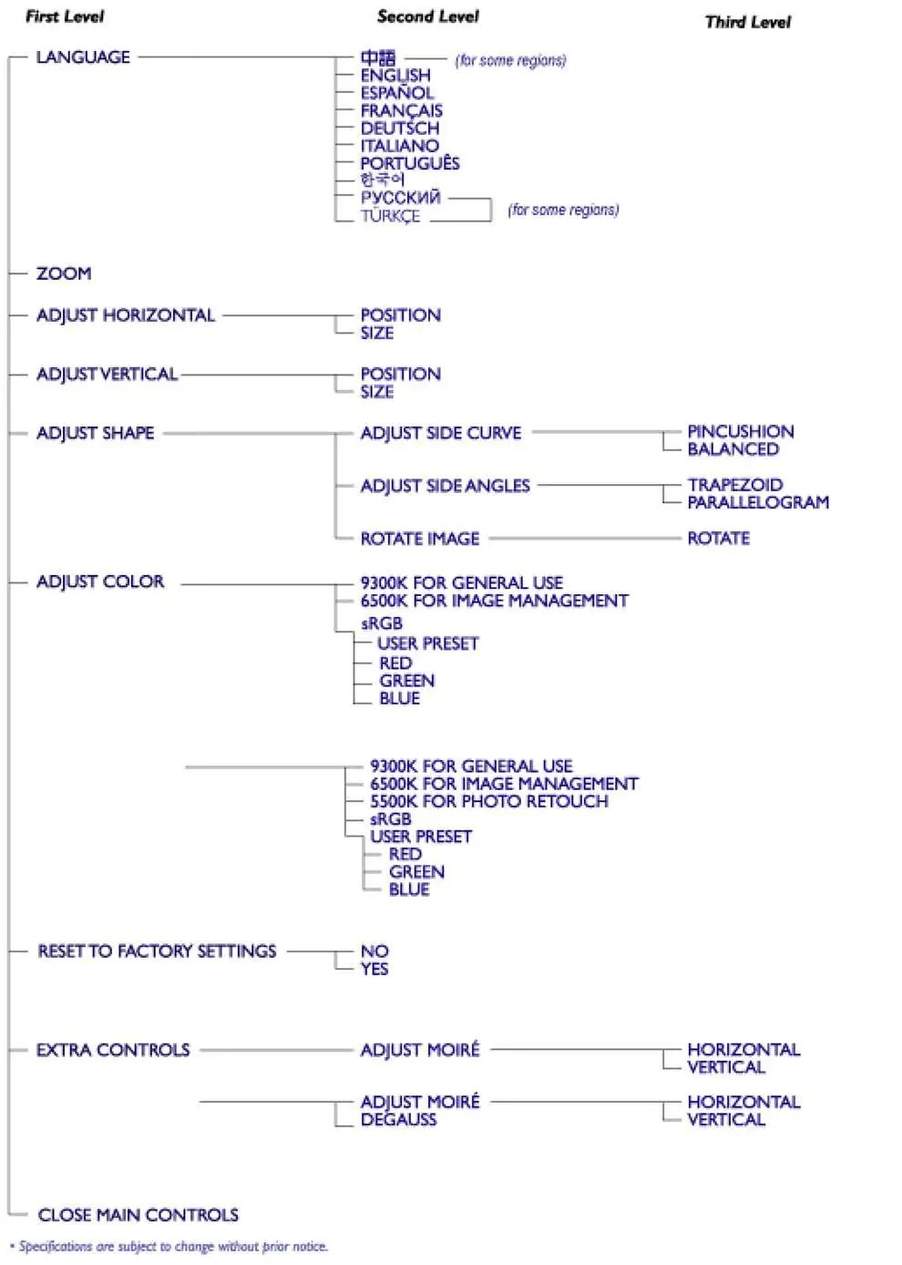
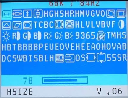
- Factory Preset Timings: Access the factory preset window by pressing the MENU key, selecting "ZOOM", and holding the zoom function for about 10 seconds.
- Purity & Convergence: Ensure 29mm spacing between the PCM assembly and the CRT stem. Adjust purity magnet rings for a complete red field, then perform convergence adjustments using the 4-pole and 6-pole magnets on the PCM assembly.
Mechanical disassembly
To perform repairs, place the unit in the service position:
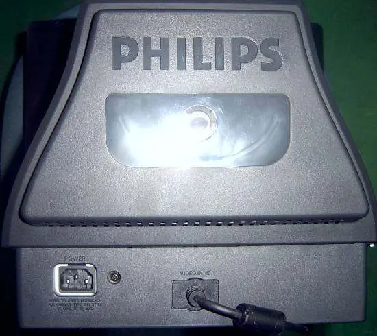
- Remove the rear cover by unscrewing the 3 designated screws.
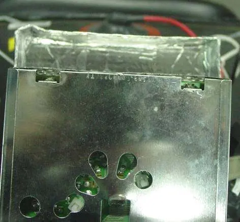
- Disconnect the video board by cutting the tip on the front frame, disconnecting the adhesive tape and ground pins from the metal shield, and cutting the tie between the CRT neck and the video board.
- Disconnect the main panel by removing the rotation coil, degaussing coil, ground-screw, BY coil, key board connector P102, ground pins, and the Hi-Pot cap.
- Remove the main board and front frame as required.
Troubleshooting
The manual includes detailed flowcharts for diagnosing common issues, including:
- No Raster: Check main PCB power supply (56V, 14V, 80V, 7V), high voltage (21.0-22.8kV), CRT heater voltage (6.3V), and screen voltage (400V-600V).
- Abnormal Display: Check video IC801 voltages, signal inputs, and FBT screen voltage.
- Power Supply: Verify variable output (60V-154.5V) and constant outputs (6.3V, 14V, 80V).
Technical specifications
- CRT: 17" (43.2cm) 90° deflection, 0.25mm phosphor dot pitch, Pure Flat.
- Scanning Frequencies: Horizontal 30kHz-86kHz, Vertical 50Hz-160Hz.
- Power Source: AC 90-264V, 50/60Hz universal.
- Power Consumption:
Manufacturer information
Philips
Practical help
Common problems
No Raster
Check main PCB power supply voltages (56V, 14V, 80V, 7V), high voltage (21.0-22.8kV), and CRT heater voltage (6.3V).
Abnormal Display
Verify IC801 pin voltages, signal inputs (0.7Vpp), and FBT screen voltage (400V-700V).
Power Supply Failure
Check AC line voltage, bridge rectifier, start circuit (R939, R940, D912, ZD903), and IC901.
Before use
- Ensure the monitor is not exposed to external magnetic fields.
- Allow 30 minutes for warm-up before performing any adjustments.
- Use a separate isolation transformer when servicing.
- Wear shatter-proof goggles when handling the picture tube.
- Ensure the signal cable is securely connected to the PC.
Specs in practice
- Horizontal Frequency
- 30kHz to 86kHz range for signal compatibility.
- Vertical Frequency
- 50Hz to 160Hz range for refresh rate.
- Video Bandwidth
- 180 MHz for high-resolution signal processing.
Images and diagrams
- Block diagram (page 48) shows the signal path from input to CRT and power supply stages.
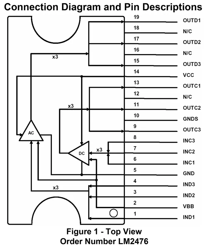
- IC block diagrams (pages 49-54) detail pinouts for SAA4849, M24C08, TDA4863AJ, NT6812, and LM2476.
- Mechanical disassembly diagrams (pages 25-27, 35) illustrate screw locations and component removal steps.
Model compatibility
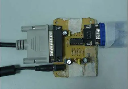
- Supports VESA DDC/2B standard.
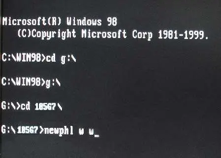
- Compatible with i486 or above PCs running Windows 95/98.
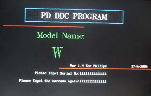
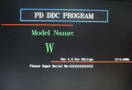
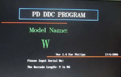
- Requires Newphl.exe (MS-DOS based) for DDC re-programming.

Manual page author
Michael Turner
Technical manual editor
Reviews PDF manuals for structure, safety notes, and practical product details so readers can find the right information quickly.