Power / Portable Power Stations
User Manual for Photonic Universe DC1212-30S and DC1212-45S DC-DC Battery Charger
A comprehensive guide for the Photonic Universe DC1212-30S and DC1212-45S DC-DC battery chargers. This manual covers installation, wiring diagrams, DIP switch configuration for various battery types, LED indicator status, and...
Table of contents
Manual images
Click an image to enlargeQuick Guide from the Manual
This DC-DC battery charger is designed for vehicles and boats to charge a target battery from a source battery. Important: The charger requires a D+ signal to operate. If your system lacks an alternator D+ signal, you must wire the D+ terminal directly to the positive terminal of the source battery to turn the charger on. Always set the correct battery type using the DIP switches while the charger is off before connecting.
Overview
The Photonic Universe DC-DC charger is a fully automatic, three-stage charger suitable for lead-acid, AGM, GEL, LiFePO4, and Lithium-ion (NCM) batteries. It features high-frequency switching and buck-boost technology. It includes protection against overheating, overvoltage, short circuits, and over-currents.
Installation
Install the charger as close to the target battery as possible in a clean, dry, and well-ventilated area. Leave at least 10 cm of space around the unit for airflow. Use cables with a cross-section of 1mm² for every 3A of maximum charging current. Fuses must be installed within 15cm of the battery terminals.
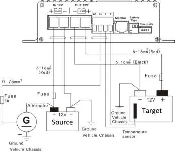
Connection Diagram
Ensure positive and negative poles are not reversed. Connect cables to the charger terminals first before connecting to the battery terminals to avoid working with live cables.
Green Terminals
The charger features a pluggable terminal block for specific connections:
- T T: Terminals for an optional temperature sensor. Highly recommended for lead-acid batteries to adjust charging voltage based on ambient temperature.
- D+: Terminal for the alternator signal (8V-16V). Controls the ON/OFF function.
- NC: Reserved spare terminal, no connection required.
Battery Configuration
Set the DIP switches according to your target battery type before powering on the charger:
- GEL: 1:ON, 2:OFF, 3:OFF (14.3V)
- Lead-acid: 1:OFF, 2:ON, 3:OFF (14.4V)
- AGM: 1:OFF, 2:OFF, 3:ON (14.7V)
- LiFePO4: 1:ON, 2:ON, 3:ON (14.4V)
- Lithium-ion (NCM): 1:OFF, 2:OFF, 3:OFF (12.6V)
LED Indicators
The charger uses three LEDs to indicate status:
- Source Battery (Yellow): Indicates source voltage status. OFF means no D+ signal.
- Charge (Green): Indicates charging status. Slow flashing means temperature issues.
- Battery Full (Green): Indicates charging stage. ON means battery is full.
- Target Battery (Red): Indicates target battery voltage status.
Protection Functions
The charger includes several safety features:
- Target battery overvoltage: Charging stops if voltage exceeds limits.
- Target battery low voltage: Buzzer alarm sounds.
- Overheating: Charging reduces or stops if internal temperature exceeds 80°C-85°C.
- Battery reverse polarity: Will blow the internal fuse.
Optional Accessories
The charger supports several optional add-ons:

- Remote meter (ACDC-RM): Displays real-time charging parameters.
- Bluetooth dongle (ACDC-BT): Allows monitoring via a mobile app.
- Temperature sensor (DCDC-TS): Measures external battery temperature for voltage adjustment.
- Circuit breakers (CB/CBR series): Can be used instead of fuses.
Practical help
Common problems
Charger will not turn on
Check the D+ signal. If no signal is present, wire the D+ terminal directly to the positive terminal of the source battery.
All LEDs flashing
Battery selection error. Turn off the charger and adjust the DIP switches to match one of the supported battery types.
Charging stopped
Check source battery voltage. If it is below 11.2V, charging stops. Also, check for overheating or reverse polarity.
Before use
- Ensure the target battery type is selected via DIP switches while the charger is off.
- Install the charger as close to the target battery as possible.
- Ensure proper ventilation with at least 10cm of space.
- Use the correct cable cross-section (1mm² per 3A).
- Install fuses within 15cm of battery terminals.
Specs in practice
- Boost charging voltage
- The voltage used during the constant current stage to charge the battery.
- Float charging voltage
- The lower voltage used to maintain the battery charge after the absorption stage.
- Temperature compensation
- Adjusts charging voltage based on ambient temperature (lead-acid only) to protect the battery.
Images and diagrams
- The connection diagram illustrates the wiring between the source battery (with alternator), the charger, and the target battery.
- It highlights the necessity of placing fuses within 15cm of the battery terminals.
- It shows the D+ signal connection required for the charger to operate.
Model compatibility
- Compatible with lead-acid, AGM, GEL, LiFePO4, and Lithium-ion (NCM) batteries.
- Lithium batteries must have a Battery Management System (BMS).
- No temperature compensation is available for lithium batteries.

Manual page author
Michael Turner
Technical manual editor
Reviews PDF manuals for structure, safety notes, and practical product details so readers can find the right information quickly.