Power / Solar Inverters
User Manual for Photonic Universe 1.5KW/3KW/5KW Solar Inverter/Charger
Quick guide for the Photonic Universe 1.5KW, 3KW, and 5KW solar inverter/charger. Includes installation steps, wiring diagrams, LCD settings, troubleshooting, and technical specifications.
Table of contents
Manual images
Click an image to enlargeQuick guide from the manual
This document provides essential instructions for the installation, operation, and maintenance of the Photonic Universe 1.5KW, 3KW, and 5KW solar inverter/charger. This unit is a multi-function device combining an inverter, solar charger, and battery charger. It is designed for indoor use on non-combustible surfaces only.
Safety Instructions
- Only qualified personnel should install this device.
- Use only deep-cycle lead-acid rechargeable batteries.
- Ensure the system is connected to a permanent grounded wiring system.
- Do not connect grounded PV modules to the inverter as this causes current leakage.
- Use a PV junction box with surge protection to prevent lightning damage.
Installation
Mounting the Unit
- Mount on a solid, non-combustible surface (e.g., concrete).
- Install at eye level for easy LCD reading.
- Ensure proper air circulation: allow approx. 20 cm to the sides and 50 cm above and below the unit.
- Maintain ambient temperature between 0°C and 55°C.
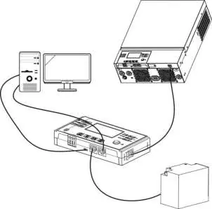
Wiring Connections
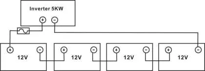
- Battery Connection: Install a separate DC over-current protector between the battery and inverter. Use recommended cable sizes (1*6AWG for 1.5KW; 1*2AWG for 3KW/5KW). Ensure correct polarity.
- AC Input/Output: Install a separate AC breaker between the inverter and the AC source (16A for 1.5KW, 32A for 3KW, 50A for 5KW). Connect Ground (yellow-green), Line (brown/black), and Neutral (blue).
- PV Connection: Install a separate DC circuit breaker between the inverter and PV modules. Ensure PV open circuit voltage does not exceed the inverter's maximum limit.
Operation
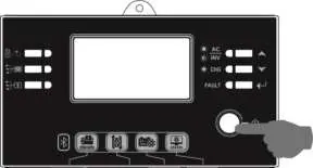
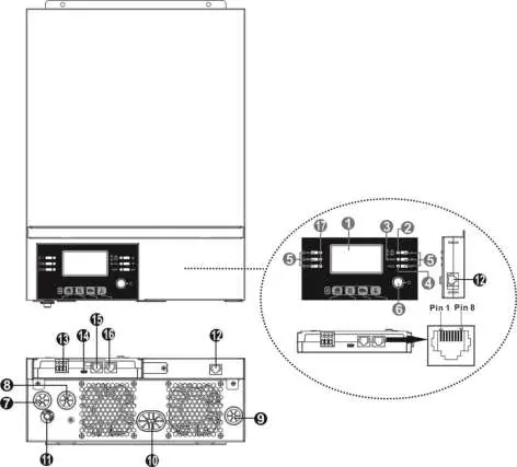
Display Panel
The front panel features an LCD display, status indicators, and function keys. The LCD provides real-time data on input/output power, battery status, and system settings.
LCD Settings
To enter setting mode, press and hold the Enter button for 3 seconds. Use Up/Down keys to navigate programs and Enter to confirm.
- Program 01 (Output Source Priority): Choose between Utility first, Solar first, or SBU (Solar-Battery-Utility) priority.
- Program 02 (Max Charging Current): Configure total charging current (utility + solar).
- Program 05 (Battery Type): Select AGM, Flooded, or User-Defined.
- Program 16 (Charger Source Priority): Set priority for battery charging sources.
Battery Equalization
This function reverses negative chemical effects like stratification and sulfation. Enable it in Program 30. You can set the interval in Program 35 or activate it immediately in Program 36.
Troubleshooting
- Unit shuts down during startup: Battery voltage too low (<1.91V/Cell). Recharge or replace battery.
- No response after power on: Battery voltage too low (<1.4V/Cell) or internal fuse tripped. Check fuse, recharge or replace battery.
- Mains exist but unit in battery mode: Input protector tripped or insufficient AC quality. Check AC breaker and wiring.
- Buzzer beeps/Red LED on: Check the fault code on the LCD. Common codes include 07 (Overload), 05 (Short circuit), and 02/03 (Temperature/Battery issues).
Technical Specifications
The inverter supports pure sine wave output. Key parameters vary by model (1.5KW, 3KW, 5KW). Refer to the full manual for detailed tables regarding Line Mode, Inverter Mode, and Charge Mode specifications.
Practical help
Common problems
Unit shuts down during startup
Battery voltage is too low (<1.91V/Cell). Re-charge or replace the battery.
No response after power on
Battery voltage is too low (<1.4V/Cell) or internal fuse tripped. Contact repair center for fuse replacement or recharge/replace battery.
Mains exist but unit works in battery mode
Input protector is tripped or AC power quality is insufficient. Check AC breaker and wiring.
Buzzer beeps continuously and red LED is on
Indicates a fault. Check the fault code on the LCD (e.g., 07 for overload, 05 for short circuit) and follow the specific troubleshooting steps in the manual.
Before use
- Ensure the installation surface is non-combustible (e.g., concrete).
- Verify battery capacity (min 100Ah for 1.5KW/3KW, 200Ah for 5KW).
- Check that cable sizes match the recommended specifications for your model.
- Install a separate DC circuit breaker between the battery and inverter.
- Install a separate AC breaker between the inverter and the AC source.
- Verify correct polarity for all battery and PV connections.
Specs in practice
- Max. PV Array Power
- Maximum wattage of solar panels supported (2000W for 1.5KW, 4000W for 3KW/5KW).
- PV Array MPPT Voltage Range
- Operating voltage range for solar panels (120Vdc-380Vdc for 1.5KW, 120Vdc-450Vdc for 3KW/5KW).
- Transfer Time
- Time to switch between utility and battery power (10ms for UPS mode, 20ms for Appliances mode).
Images and diagrams
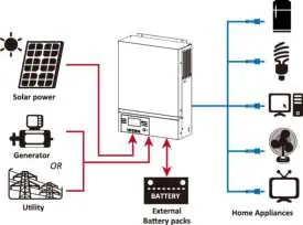
- Hybrid Power System: Shows the integration of solar panels, utility/generator, battery packs, and home appliances.
- Product Overview: Identifies the LCD display, function buttons, and all input/output ports.
- Battery Connection: Illustrates the correct wiring configuration for battery packs.
Model compatibility
- PV Modules: Only single crystalline, poly crystalline (class A), and CIGS modules are acceptable.
- Batteries: Use only deep-cycle lead acid rechargeable batteries.

Manual page author
Michael Turner
Technical manual editor
Reviews PDF manuals for structure, safety notes, and practical product details so readers can find the right information quickly.