Health / Laboratory Equipment
User Manual for Vanguard 125V 15A Connector
Quick guide for the Vanguard 125V 15A Connector (63125/63126). Includes wiring instructions, torque specifications, and safety guidelines for proper installation.
Table of contents
Manual images
Click an image to enlargeQuick Guide
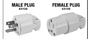
This manual provides instructions for the Vanguard 125V 15A Connector (Models 63125 and 63126). This device is intended for use with 16-3 round jacket cords. Installation must be performed by a qualified person, and all conductors must be de-energized before wiring.
Specifications
- Rating: 125VAC / 15A
- Wire Capacity: 16 AWG, 3 wire, round jacket
- NEMA Configuration: 5-15R / 5-15P
- Compatible Cord Types: SJT, ST, S, SE, SJ, SJE
Wiring Preparation
Before beginning, ensure the power is disconnected. Prepare the cord as follows:
- Select the correct end of the cord to ensure easy insertion.
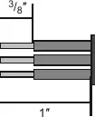
- Strip the cord jacket and conductors as shown in Figure A.
- Twist the strands (do not tin the conductors).
- Strip Lengths: 1 inch for the outer jacket, 3/8 inch for individual conductors.
Wiring Instructions
- Open the connector by separating its body and shell. Note that the plug/connector is keyed to the shell.
- Slip the outer shell onto the cord. Adjust cord clamps if necessary based on cord size.
- Insert conductors into the identified terminal pockets:
- Green wire: Green terminal pocket.
- White wire: White terminal pocket.
- Black wire: Brass terminal pocket.
- Tighten terminal screws to 20 inch lb.
Assembly
- Slip the shell into the front section by aligning the key on the body with the key in the shell.
- Evenly tighten assembly screws to 14 inch lb.
- Evenly tighten cord grip screws to 14 inch lb.
Safety Information
- Disconnect power before connecting.
- Inspect the device before connecting and before every use. Do not use if parts are loose or damaged.
- Wear ANSI-approved safety goggles during installation.
- Use only as intended. Do not expose to moisture or rain. Keep off the ground.
- Tighten all connections securely.
Practical help
Common problems
Device not functioning after installation
Verify that all conductors are inserted into the correct terminal pockets (Green to Green, White to White, Black to Brass) and that screws are tightened to 20 inch lb.
Cord is loose or slipping
Ensure the cord grip screws are tightened to 14 inch lb.
Before use
- Disconnect power source before starting installation.
- Verify wire is 16 AWG, 3-wire round jacket.
- Ensure cord type is compatible (SJT, ST, S, SE, SJ, or SJE).
- Wear ANSI-approved safety goggles.
- Check that all parts are intact and undamaged.
Specs in practice
- Terminal Torque
- Tighten terminal screws to 20 inch lb for a secure electrical connection.
- Assembly Torque
- Tighten assembly and cord grip screws to 14 inch lb.
- Strip Length
- Strip 1 inch of the outer jacket and 3/8 inch of the individual conductors.
Images and diagrams
- Figure A illustrates the required stripping dimensions for the cord jacket (1 inch) and the individual conductors (3/8 inch).
Model compatibility
- Use copper wire only.
- Device must be installed by a qualified person.
- Compatible with NEMA 5-15R / 5-15P configurations.

Manual page author
Emily Carter
User documentation editor
Prepares concise manual descriptions and highlights the most useful setup, operation, and maintenance information for readers.