HVAC / Water Heaters
Rinnai Infinity 14-17i Flue Gas Exhaust Configuration Guide
Technical guide for Rinnai Infinity 14-17i water heater flue gas exhaust configurations. Includes installation diagrams, compatible models, pipe diameters, and maximum exhaust distances for wall, roof, and split systems.
Table of contents
Manual images
Click an image to enlargeImportant Information
This document provides technical specifications and configuration requirements for the flue gas exhaust systems of Rinnai Infinity 14-17i water heaters. It details the necessary components, pipe diameters, and maximum allowable distances for various installation types, including direct wall, distant wall, roof, and split exhaust systems.
Exhaust System Configurations
The system supports four primary installation configurations. Users must select the configuration that matches their specific appliance model and installation environment.
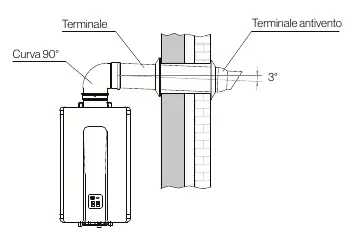
Direct Wall Exhaust
This is the standard configuration for wall-mounted exhaust. It utilizes coaxial piping (60/100 or 80/125) to vent directly through the wall.
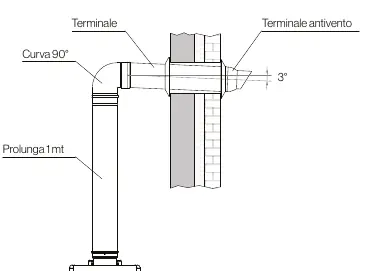
Distant Wall Exhaust
This configuration allows for longer pipe runs using extensions. It is suitable for installations where the appliance is located further from the external wall.
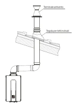
Roof Exhaust
Designed for vertical exhaust routing through the roof. Requires specific roof flashing and terminal components.
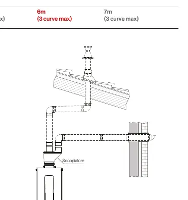
Split Exhaust System
This system separates the intake and exhaust pipes. It allows for greater flexibility in positioning the intake and exhaust terminals independently.
Installation Guidelines
- Slope: Maintain a 3° slope for the terminal to prevent condensate from flowing back into the appliance.
- Condensate Management: For condensing appliances or those equipped with a condensate trap, the slope can be directed towards the appliance.
- Components: Use the vertical condensate trap (FOT-HX60-A13) where required by the configuration.
- Intake Grille: It is recommended to combine the intake grille installation with the 90° curve FOT-KS080-005.
Practical help
Common problems
Condensate flowing back into the appliance
Ensure the terminal has a 3° slope away from the appliance, unless using a condensing model or a condensate trap.
Exceeding maximum pipe length
Check the specific configuration table for your model; exceeding the maximum distance or curve count will impair system performance.
Before use
- Verify the specific model (e.g., REU-N2635FFC-E) matches the configuration table.
- Determine the required pipe diameter (60/100 coax or 80/125 coax).
- Confirm the maximum allowed distance for the chosen configuration.
- Ensure the number of curves does not exceed the maximum allowed (e.g., 2 or 3 curves).
- Check if a vertical condensate trap is required for your installation.
Images and diagrams
- The diagrams illustrate the required slope (3°) for the exhaust terminal.
- The tables list compatible models, pipe diameters, and maximum lengths for each configuration type.
Model compatibility
- Configurations are specific to Rinnai Infinity 14-17i models.
- Ensure the correct FOT- series codes are used for the specific installation type.

Manual page author
Emily Carter
User documentation editor
Prepares concise manual descriptions and highlights the most useful setup, operation, and maintenance information for readers.