HVAC / Water Heaters
Installation Manual for Viessmann Vitocell 100-V/100-W Storage Water Heater
Professional installation guide for Viessmann Vitocell 100-V and 100-W storage water heaters. This manual covers setup, insulation assembly, electrical and sensor connections, water circuit integration, and technical specifications.
Table of contents
Manual images
Click an image to enlargeQuick guide from the manual
This document is intended exclusively for authorized professionals. It provides installation, connection, and maintenance instructions for the Viessmann Vitocell 100-V and 100-W storage water heaters. Ensure the installation room is frost-protected and that all local safety regulations are followed.
Safety instructions
- Professional use only: Installation and electrical work must be performed by authorized specialists.
- Electrical safety: Isolate the system from the power supply before starting work and secure against reconnection.
- Hot surfaces: Allow the device to cool down before maintenance. Avoid touching uninsulated pipes.
- Static discharge: Touch grounded objects (e.g., heating pipes) before handling electronic components to prevent damage.
- Heavy parts: Use appropriate safety gear and handle components with care.
Installation preparation
Before installation, ensure the room is frost-protected and draft-free. If there is a risk of frost, the heater must be drained when not in operation. Ensure sufficient space is provided for maintenance, particularly for the 750L and 950L models, which require at least 850mm of clearance for anode replacement.

Installation steps
Storage water heaters up to 300L
- Install the storage temperature sensor and thermometer probe.
- Check the anode connection, mount the cover, and apply the type plate.
Storage water heaters 500L
- Install the thermal insulation and check the anode connection.
- Mount the thermometer probe and temperature sensor.
Storage water heaters 750L to 950L
- Position the heater and align it using the adjustable feet.
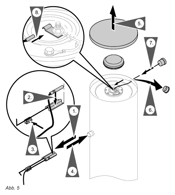
- Check the anode connection.
- Install the thermometer probe and storage temperature sensor.
Insulation and finishing
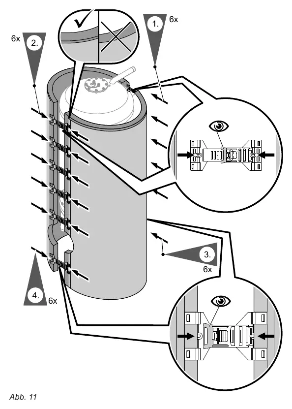
For 500L to 950L models, the thermal insulation jacket must be installed. Ensure no fleece residue enters the storage connections. Use two people for this assembly. Secure the clip fasteners on the rear and front sides of the jacket until they lock into place.
Connections
Heating water side
- Connect all pipes using detachable fittings.
- Seal unused connections with gunmetal caps.
- Ensure the temperature controller and safety temperature limiter are set so the water temperature does not exceed 95°C.
Drinking water side
- Observe DIN 1988 and DIN 4753 standards.
- Equip the circulation line with a circulation pump, check valve, and timer.
- Install a type-tested diaphragm safety valve in the cold water line to protect against overpressure. The blow-off line must not be obstructed.
Technical data
The manual includes detailed tables for dimensions, weights, and connection sizes for all models (160L to 950L). Refer to the technical data section for specific operating pressures, test pressures, and heating performance ratings.
Disposal
Viessmann products are recyclable. Do not dispose of components or operating fluids in household waste. Use the Viessmann-organized disposal system or local collection points.
Manufacturer information
Viessmann Climate Solutions
Practical help
Common problems
Frost damage risk
Install in a frost-protected room or drain the heater completely if it will not be operated during freezing conditions.
Static electricity damage
Touch a grounded object (e.g., water pipe) before touching electronic components to discharge static electricity.
Insulation debris
Ensure no fleece residue from the insulation jacket enters the storage tank connections during assembly.
Before use
- Verify the installation room is frost-protected and draft-free.
- Ensure sufficient clearance for maintenance (min. 850mm for 750/950L models).
- Check that the magnesium anode is properly connected.
- Ensure the safety valve is installed in the cold water line and is not obstructed.
- Verify all pipe connections are tight and sealed with appropriate fittings.
Specs in practice
- Max. Operating Pressure (Heating)
- 16-25 bar depending on the specific model and configuration.
- Max. Operating Pressure (Water)
- 10 bar (1 MPa).
- Max. Water Temperature
- 95°C.
Images and diagrams
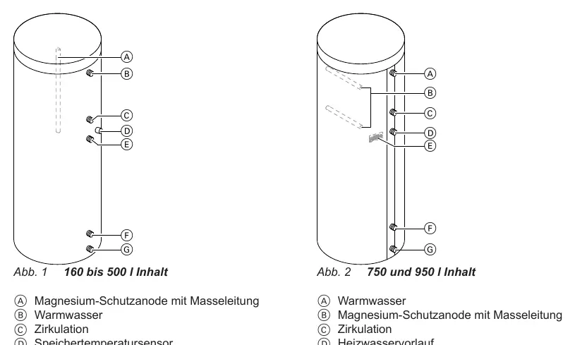
- Connection diagrams illustrate the layout of heating flow/return, circulation, and cold/hot water ports.
- Installation diagrams show the correct placement of sensors and the assembly of the insulation jacket.
Model compatibility
- Suitable for systems according to DIN 1988, EN 12828, and DIN 4753.
- Requires professional installation by authorized personnel.

Manual page author
David Miller
Documentation analyst
Organizes user manual content into clear summaries, with attention to model details, product context, and everyday usability.