Industrial / Door Hardware
Installation Guide for Sargent 10 Line and 10X Line Latch Extension
Quick installation guide for Sargent 10 Line and 10X Line Bored Locks Latch Extension. Includes step-by-step assembly instructions for 3-3/4" and 5" backsets, alignment tips, and testing procedures.
Table of contents
Manual images
Click an image to enlargeQuick Installation Guide
This document provides instructions for installing the latch extension assembly on Sargent 10 Line and 10X Line Bored Locks. It is compatible with 3-3/4" and 5" backsets. Proper orientation of the yoke assembly is critical for the lock to function correctly.
Assembly Instructions
Follow these steps to assemble the latch extension:
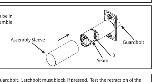
- Insert Yoke Assembly: Place the yoke assembly into the extension housing. Ensure the yoke fork "A" faces the seam and cutaway "B". This specific orientation is required for proper operation.
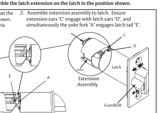
- Attach to Latch: Connect the extension assembly to the latch. Ensure the extension ears "C" engage with the latch ears "D", and simultaneously ensure the yoke fork "A" engages the latch tail "E".
- Install Sleeve: Ensure the seam and cutaway "B" are on the same side as the deadlocking guardbolt. Slide the assembly sleeve over the unit to secure both the latch and the latch extension.
Testing and Verification
After installation, verify the deadlocking function:
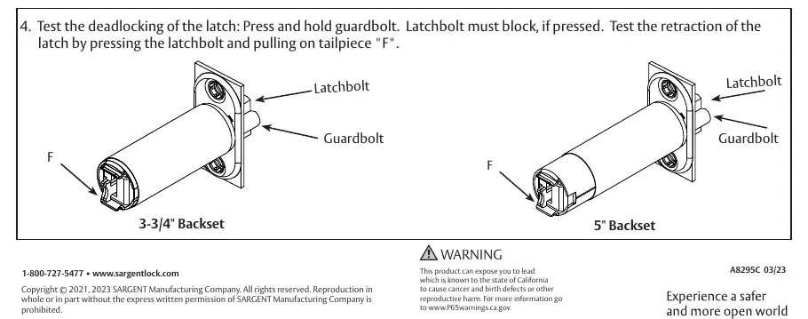
- Press and hold the guardbolt.
- The latchbolt must be blocked and unable to move when pressed.
- Test the retraction of the latch by pressing the latchbolt and pulling on the tailpiece "F".
Practical help
Common problems
Latch does not deadlock
Ensure the guardbolt is pressed and the latchbolt is blocked. Verify the seam and cutaway are aligned with the guardbolt.
Extension assembly does not fit
Verify the yoke fork orientation and ensure extension ears engage with latch ears.
Before use
- Verify backset size (3-3/4" or 5")
- Ensure all parts (yoke, housing, sleeve) are present
- Check orientation of yoke fork before insertion
Images and diagrams
- Diagrams show the alignment of the yoke fork with the seam and cutaway.
- Illustrations demonstrate the engagement of extension ears with latch ears.
- Testing procedure shows the interaction between the guardbolt and latchbolt.
Model compatibility
- Compatible with Sargent 10 Line and 10X Line Bored Locks.
- Designed for 3-3/4" and 5" backsets.

Manual page author
David Miller
Documentation analyst
Organizes user manual content into clear summaries, with attention to model details, product context, and everyday usability.