Industrial / Door Hardware
Installation Guide for SARGENT 10X Line Cylindrical Lockset
A comprehensive installation and configuration guide for the SARGENT 10X Line Cylindrical Lockset. Includes step-by-step instructions for door preparation, adjusting for door thickness, latch and cylinder installation, and lock timing...
Table of contents
Manual images
Click an image to enlargeImportant Information
The accuracy of door preparation is critical for the proper functioning and security of the 10X Line Cylindrical Lockset. Misalignment can cause premature wear and reduced security. Always verify the backset before marking and drilling the door. Do not force the lock during installation; if the lockbody does not engage the latch easily, check the door preparation for errors.
Tools Required
- #2 Phillips screwdriver
- Lever release tool (provided)
- 5/16" drill bit
- 1/8" drill bit
- 5/32" drill bit
Door Preparation
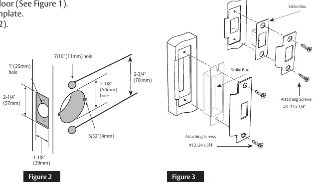
- Use template A8290 to mark the door.
- Drill the door according to the template.
- Verify the dimensions (backset must match the latch).
- Install the strike.
Latch Installation
Insert the latch into the door, ensuring the bevel edge of the bolt faces the strike plate. Attach using the two provided #8-32 x 3/4" screws. The deadlocking latch must stop on the strike when the door is closed.
Adjusting for Door Thickness
The lock is factory preset for 1-3/4" (44mm) doors. To adjust for other thicknesses:
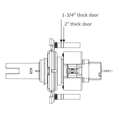
- Remove the trim assembly from the lockbody.
- Rotate the mounting plate to adjust for the proper door thickness.
- For a 2" thick door, the inside face of the mounting plate should be flush with the face of the bearing.
- Verify the position using markings on the through-bolt stud or by measuring from the inside surface of the mounting plate to the centerline of the retractor.
- Reassemble the outside trim assembly to the lockbody.
Installing Outside Assembly
Insert the lockbody into the door from the outside, ensuring the lockbody hooks the latch case and the retractor engages the bolt tail. Do not force the installation. The latch bolt tail should be centered in the depth of the retractor.
Installing Inside Components
- Remove the rose from the inside spring housing assembly.
- Align and insert the inside spring housing onto the installed lockbody.
- Install screws to tighten the lock to the door.
- Orient the dimples on the side of the rose horizontally at the 3 and 9 o'clock positions, aligning them with the openings on the spring housing assembly.
- Install the rose onto the inside spring housing assembly.
- In the unlocked position, verify the button is adjusted properly.
- Install the inside lever.
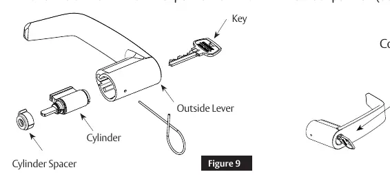
Cylinder Installation
Before installing, use a flat blade screwdriver to rotate the cam until the driver points are in the 6 and 12 o'clock positions. For standard cylinders, ensure the cylinder spacer is "snapped" onto the cylinder before installing into the outside trim assembly.
Lock Timing
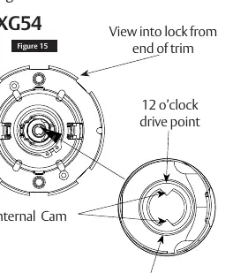
Timing is required if cylinders were not factory-installed. Remove the cylinder lever to view the internal cam. Use a slotted screwdriver to rotate the cam fully clockwise (or counter-clockwise depending on the function) until the drive points are at the 6 and 12 o'clock positions. Test the cylinder with the key before closing the door.
Miscellaneous Options
The manual includes specific instructions for:
- 1-3/8" door installations (requires adapter plates).
- Installation of single and double lever pulls (10XU93, 10XU94).
- Lever options for Schlage and Yale cores.
- Hotel function timing adjustments (10XG50).
Practical help
Common problems
Lockbody does not engage latch easily
Do not force the lock. Check door preparation for errors.
Key does not operate properly (Hotel function)
If the operating key works in the locked position, turn the interior cap out (CCW) 1/2 turn. If the emergency key fails in the locked position, turn the interior cap in (CW) 1/2 turn.
Latch bolt tail not centered
Refer to the 'Adjusting for Door Thickness' section to properly adjust the mounting plate.
Before use
- Verify backset before marking and drilling the door.
- Ensure the bevel edge of the bolt faces the strike plate.
- Check door thickness (factory preset is 1-3/4").
- Verify cylinder cam is at 6 and 12 o'clock position before installation.
- Test for proper operation before closing the door.
Images and diagrams
- Figure 2: Drilling dimensions for the door.
- Figure 5a/5b: Mounting plate adjustment for different door thicknesses.
- Figure 15: Internal cam alignment for lock timing.
- Figure 22-27: Hotel function timing adjustment steps.
Model compatibility
- Compatible with 1-3/8", 1-3/4", 2", and 2-1/4" thick doors.
- Supports Standard, Interchangeable (SFIC), and Removable Cores.
- Specific functions (10XG08, 10XG53, etc.) require specific timing procedures.

Manual page author
Michael Turner
Technical manual editor
Reviews PDF manuals for structure, safety notes, and practical product details so readers can find the right information quickly.