Industrial / Door Hardware
Installation Manual for Sargent 10X Line Electrified Bored Lock
Quick installation and wiring guide for the Sargent 10X Line Electrified Bored Lock. Includes electrical specifications, fail-safe/fail-secure configuration, and wiring diagrams.
Table of contents
Manual images
Click an image to enlargeQuick Guide from the Manual
The Sargent 10X Line Electrified Bored Lock is designed for access control applications. Key installation requirements include verifying the door preparation using Template 4756 (or 4753 for BHW trim), ensuring the correct voltage (10.2VDC to 26.4VDC) is applied, and configuring the Fail Safe/Fail Secure mode via the internal DIP switch before installation.
Installation Notes
- Doors with ASSA ABLOY ElectroLynx connectors are pre-wired.
- For doors without ElectroLynx connectors, use a Retrofit Harness or hard wire the connection.
- The lock is polarity sensitive.
- Power must be supplied by UL294 and ULC-60839 Class 2 Power Limited power supplies or Listed Access Control units.
- Wiring must comply with National Electrical Code (ANSI/NFPA70), CSA 22.1, and local codes.
Electrical Specifications
- Operating Voltage: 10.2VDC to 26.4VDC.
- Current Draw: 10mA continuous; 500mA peak.
- Voltage Warning: Do not exceed 30VDC to avoid damaging the lock.
Lock Configuration
The lock can be configured for Fail Safe or Fail Secure operation. The DIP switch is located on the lock body and must be accessed prior to installation.
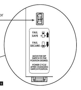
- Fail Secure: Applying power unlocks the door.
- Fail Safe: Applying power locks the door.
- Important: Power cycling is required after changing the switch position.
Installation Procedure
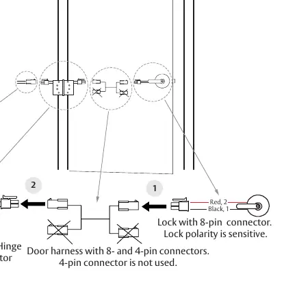
- Plug the 8-pin connector from the lock into the 8-pin connector for the wiring harness through the door.
- Plug the 8-pin connector from the door harness into the 8-pin hinge connector.
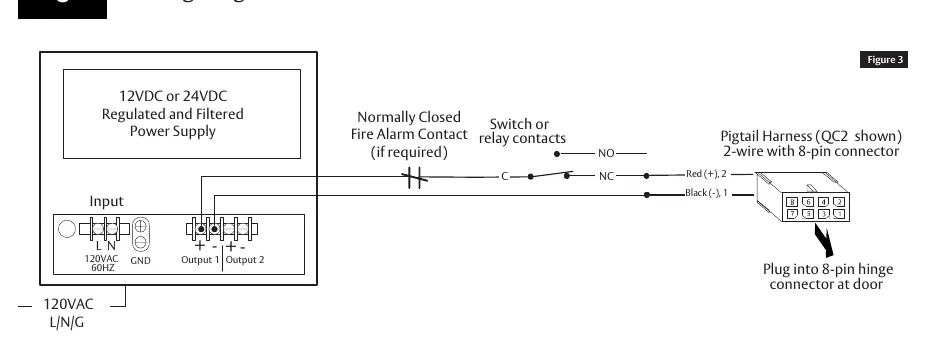
- Connect the hinge connector to the transformer or power supply.
- Test the lock operation (Fail Secure: power unlocks; Fail Safe: power locks).
Wiring Diagrams
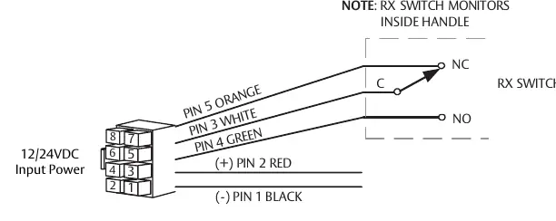
The manual provides specific diagrams for connecting the power supply and the Request to Exit (RX) switch. Ensure all connections are secure and follow the provided wire gauge chart to prevent voltage drop over long wire runs.
Practical help
Common problems
Lock not operating correctly
Verify that the input voltage is between 10.2VDC and 26.4VDC and that the polarity is correct.
Incorrect Fail Safe/Fail Secure behavior
Ensure the DIP switch is set to the desired position before installation and perform a power cycle after changing the switch position.
Lock damaged during installation
Ensure the voltage does not exceed 30VDC and that the wiring is not shorted.
Before use
- Verify door preparation using Template 4756 (or 4753 for BHW trim).
- Ensure the power supply meets UL294/ULC-60839 Class 2 requirements.
- Check the wire gauge requirements based on the total wire run length.
- Determine if the door uses ElectroLynx connectors or requires hard wiring.
- Set the Fail Safe/Fail Secure DIP switch before installing the lock.
Specs in practice
- Operating Voltage
- 10.2VDC to 26.4VDC. Exceeding 30VDC may damage the lock.
- Current Draw
- 10mA continuous; 500mA peak current draw.
Images and diagrams
- Figure 1: DIP switch location for configuring Fail Safe or Fail Secure modes.
- Figure 2: Wiring harness connection path from the lock through the door to the electric hinge.
- Figure 3: Wiring diagram for connecting the power supply.
- Figure 4: Wiring diagram for the Request to Exit (RX) switch.
Model compatibility
- Compatible with ASSA ABLOY ElectroLynx connectors.
- For non-ElectroLynx doors, a Retrofit Harness is required.
- Indoor use only (Environmental class: indoor).

Manual page author
David Miller
Documentation analyst
Organizes user manual content into clear summaries, with attention to model details, product context, and everyday usability.