Industrial / Door Hardware
Sargent 10X Line Cylindrical Lever Lock Parts Manual
Comprehensive parts manual for the Sargent 10X Line Cylindrical Lever Lock. This guide provides exploded views, part numbers for lockbodies, latches, strikes, cylinders, and levers, along with essential ordering information for maintenance...
Table of contents
Manual images
Click an image to enlargeQuick Guide to the Parts Manual
This manual is designed to help you identify and order replacement parts for the Sargent 10X Line Cylindrical Lever Lock. It contains exploded views, part number tables for various configurations, and specifications for latches, strikes, and cylinders. Always verify your specific door thickness, function, and finish before ordering parts.
Exploded View and Components
The exploded view on page 3 illustrates the assembly order of the lock. Key components include:
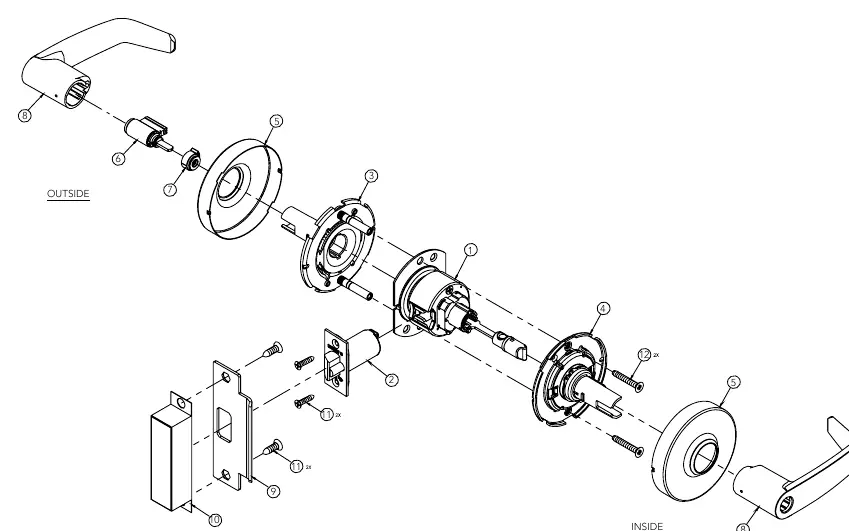
- Lockbody with Mounting Plate (Item 1)
- Latch (Item 2)
- Spring Housing Assemblies (Items 3 & 4)
- Roses (Item 5)
- Cylinder and Spacer (Items 6 & 7)
- Lever (Item 8)
- Strike and Strike Box (Items 9 & 10)
Lockbodies and Mounting
Page 4 provides part numbers for mechanical and electrified lockbodies. Selection depends on the door thickness (1-3/8" to 2" or 2-1/4") and the specific function (e.g., Storeroom, Classroom, Passage). Note that some functions include a finished button.
Spring Housing Assemblies
Page 5 details the spring housing assemblies required for different functions and door thicknesses. Ensure you select the correct part number based on whether the housing is for the inside or outside, and if it is compatible with specific cylinder types like Keso or Yale LFIC.
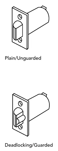
Latches and Strikes
Page 7 covers latch specifications, including backset (2-3/8", 2-3/4", 3-3/4", 5") and throw length. Page 8 details strike options, including the standard 4-7/8" curved lip strike and the 2-3/4" option, along with ANSI wrought strike boxes.
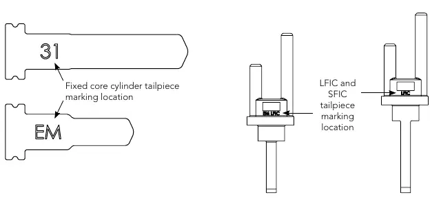
Cylinders and Tailpieces
Pages 9-11 provide extensive tables for fixed core, Large Format Interchangeable Core (LFIC), and Small Format Interchangeable Core (SFIC) cylinders. Use the tailpiece identification markings (e.g., 31, EM) shown on page 11 to ensure the correct tailpiece is selected for your cylinder type.
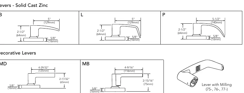
Levers and Finishes
Page 12 lists available lever styles (B, L, P, MB, MD, MW, ND) and milling options. Page 13 provides a comprehensive list of available finishes and instructions on how to order parts by specifying quantity, part number, finish, and description.
Practical help
Common problems
Identifying the correct latch backset
Refer to the Latches section (page 7) to match your door's backset (2-3/8", 2-3/4", 3-3/4", or 5").
Determining the correct cylinder tailpiece
Check the tailpiece markings (e.g., 31, EM) and refer to the Cylinders and Tailpiece Packs section (pages 9-11) to match the correct pack.
Ordering replacement parts
Provide the quantity, part number, finish, and hand (if required) as shown in the 'How to Order Parts' section on page 13.
Before use
- Verify the door thickness (1-3/8" to 2-1/4").
- Identify the required lock function (e.g., Storeroom, Passage, Classroom).
- Check the existing strike type (ANSI 4-7/8" or 2-3/4").
- Confirm the lever style and finish required.
- Determine if the lock is mechanical or electrified.
Images and diagrams
- The exploded view on page 3 shows the assembly order of the lockbody, spring housings, roses, and levers.
- Tailpiece identification markings are shown on page 11 to help match the correct cylinder.
Model compatibility
- Ensure the chosen cylinder/core is compatible with the lock function.
- Some parts, such as screw packs, must be ordered separately.

Manual page author
Emily Carter
User documentation editor
Prepares concise manual descriptions and highlights the most useful setup, operation, and maintenance information for readers.