Industrial / Door Hardware
Installation Instructions for Sargent 1130-HU Series Door Closer
A comprehensive installation and adjustment guide for the Sargent 1130-HU Series non-handed door closer. This manual covers mounting configurations for regular, top jamb, and parallel arm setups, along with detailed instructions for spring...
Table of contents
Manual images
Click an image to enlargeQuick Guide
The Sargent 1130-HU Series is a non-handed door closer with an adjustable spring size of 1-6. Installation requires determining the door hand, selecting the appropriate mounting configuration (Regular, Top Jamb, or Parallel Arm), and performing final adjustments to the valves and spring power. Always ensure the door and frame are properly reinforced before installation.
Safety Information
- Do not install these door closers on the exposed side (weather side) of exterior doors.
- Doors should be hung on ball bearing or anti-friction hinges.
- A separate door stop is recommended.
- Door and frame must be properly reinforced.
- Use of a power drill will void the warranty.
- Keep fingers away from moving parts when the arm is under tension.
Tools Required
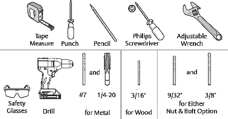
- Tape measure
- Punch
- Pencil
- Philips screwdriver
- Adjustable wrench
- Safety glasses
- Drill (with specific bits for metal or wood as detailed in the manual)
Determining Door Hand
Identify if your door is Left Hand (LH) or Right Hand (RH) by standing on the pull side of the door. If the hinges are on the left, it is a Left Hand door. If the hinges are on the right, it is a Right Hand door. Reverse handing applies if the door opens away from you.
Installation Procedures
The manual provides specific steps for three mounting types:
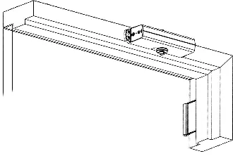
Regular Arm Installation
Mount the closer body on the door and the arm on the frame. Follow the dimension chart provided in the manual to position the closer correctly based on the desired opening angle (up to 180 degrees).
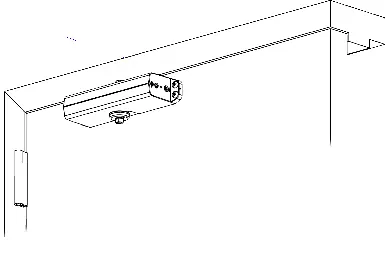
Top Jamb Mount
Mount the closer body on the frame and the arm on the door. Ensure the closer is positioned according to the specific dimensions for the desired opening angle.
Parallel Arm Installation
Mount the closer body on the door and the arm on a soffit plate attached to the frame. This configuration requires specific attention to the soffit plate installation and arm rotation.
Closer Adjustments
Adjustments should be made using the provided hex wrench. Never force valves out of the closer.
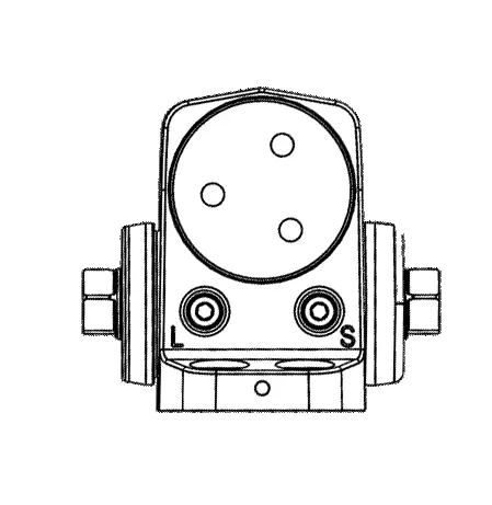
- Latch: Controls the closing speed at the end of the cycle.
- Sweep: Controls the closing speed for the majority of the cycle.
- Backcheck: Provides resistance when the door is opened forcefully.
- Spring Power: Adjust the spring power based on the door size. The door must be open to adjust the spring closing power.
Adjust the closing time speed between 3 and 7 seconds from 90 degrees to 0 degrees. Do not completely open valves, as this will cause leaks.
Practical help
Common problems
Valves leaking
Do not completely open the valves. Only turn them as much as necessary for the desired speed.
Door closing too fast or too slow
Adjust the Latch and Sweep valves using the provided hex wrench. Turn clockwise to slow down, counter-clockwise to speed up.
Improper installation
Ensure the door and frame are properly reinforced and that the correct mounting hardware is used for the door material (wood, metal, or hollow metal).
Before use
- Verify door and frame are properly reinforced.
- Ensure hinges are ball bearing or anti-friction type.
- Check door size against the spring power chart to determine required turns.
- Gather all necessary tools including drill, tape measure, and hex wrench.
- Confirm the mounting configuration (Regular, Top Jamb, or Parallel) matches your door setup.
Specs in practice
- Spring Power
- Adjustable size 1-6. Determines the force required to open and close the door based on door width.
Images and diagrams
- Regular Arm: Closer body on door, arm on frame.
- Top Jamb Mount: Closer body on frame, arm on door.
- Parallel Arm: Closer body on door, arm on soffit plate attached to frame.
Model compatibility
- Not for use on the exposed side of exterior doors.
- Requires specific reinforcement for door and frame.
- Use of a power drill will void the warranty.

Manual page author
Emily Carter
User documentation editor
Prepares concise manual descriptions and highlights the most useful setup, operation, and maintenance information for readers.